
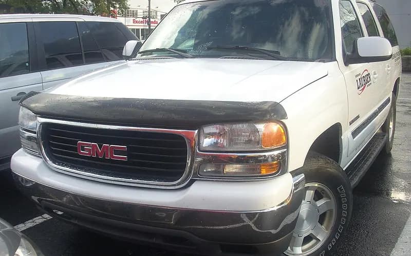
← Look into the faults of the GMC Yukon XL
Symptom
Leak: possible causes and documented repairs — 2000–2006 GMC Yukon XL
Of the records of the 2000–2006 GMC Yukon XL, 142 state “Leak” (Owner complaint: 76, Recall: 11, Manufacturer communication: 55). The technical documents say how to deal with 21 of its possible causes. They are listed by the number of matching records, most first.
Narrow it by model year, engine and more
Causes the technical documents say how to deal with (21)
Brake pipe (brake line) corrosion and rupture
43 matching records
The pipes' steel-copper construction is vulnerable to galvanic corrosion if exposed to the environment.
NHTSA found the failures came with general excessive corrosion over most of the pipe assembly and appear to be expected wear-out of the coating in severe-corrosion states.
How to tell
What to do
- In the joint inspections, scaling or flaking corrosion was taken as indicating the onset of metal loss and given the second lowest ranking (2); a leaking or previously repaired pipe was the lowest (1).
- GM noted that pipes with excessive flaking corrosion can only be fully evaluated, including remaining service life, by removing them, cleaning off the corrosion and sectioning them to assess remaining wall thickness.
- The inspections found no specific location where corrosion was visually more severe and no pattern between vehicles.
- Service records of incident vehicles also indicate that repairs are not isolated to a specific location or brake pipe.
6 more steps ·All steps, part numbers and sources (4 sources) →
Engine Block
5 matching records
Hydro-boost brake assist and power steering share one hydraulic supply (four campaigns)
4 matching records
Some vehicles were built with an out-of-specification hydro-boost housing relief valve bore.
The hydraulic brake booster pressure accumulator may crack and separate from the hydro-boost assembly during normal operating conditions.
What to do
- Perform the "Power Steering System Test" found in SI and make any necessary repairs based on system diagnosis.
- To tell whether a 670 gear box is fitted, inspect the mounting bolts that attach the stub shaft housing; a 670 gear box has only 3 mounting bolts.
- The PI document instructed technicians to diagnose the vehicle using the Power Steering Test Procedures if an owner complained about difficulty steering during "parking lot type maneuvers"; if the vehicle passed this test, no work was required, as GM viewed this as a normal phenomenon.
- Dealers replace the hydro-boost relief valve.
8 more steps ·All steps, part numbers and sources (7 sources) →
Single-cylinder misfire (P0300-P0308) and/or chirp, squeak or tick at camshaft speed: worn cam lobe / lifter, valve or valve spring
4 matching records
Customers may complain of an SES light, engine misfire and/or engine noise.
A verified noise is not eliminated by canceling fuel injectors and occurs at camshaft speed (half of crankshaft speed).
How to tell
What to do
- If pressing on the valve side of the rocker changes the noise, a lifter and/or cam lobe concern on that cylinder is most likely.
- The misfiring/ticking cylinder should have less cam lobe lift than comparison cylinders if a worn lifter roller and/or cam lobe is the cause.
- During the noise, press with a wooden hammer handle on the rocker arms at the valve side, push rod side, and side of the rocker to find which one is making noise.
- Measure the cam lobe lift at the push rod side of the rocker arm.
8 more steps ·All steps, part numbers and sources (6 sources) →
Cylinder
4 matching records
Mid-frame cross member tear could puncture fuel tank in angled frontal impact - recall 03V-019
3 matching records
In a sufficiently severe 30-degree left angle frontal impact, a tear could develop in the mid-frame cross member where it attaches to the left frame rail.
What to do
- Dealers install a fuel tank shield.
Engine fuel rail crossover tube retainer screws may break (5.3L RPO L59) - recall 04V-376
2 matching records
The engine fuel rail crossover tube retainer screws were not manufactured to specification and may break.
The failed screw was harder than specification; the over-hardening came from a conveyor in an induction hardening operation at the fastener plant stopping or slowing excessively, exposing the screws to the hardening for too long.
What to do
- Check for leaks: ignition ON with the engine OFF for 2 seconds, ignition OFF for 10 seconds, ignition ON with the engine OFF, then visually inspect for fuel leaks.
- Dealers inspect the fuel rail crossover tube and replace the retainer screws if necessary.
- Hold the fuel crossover tube retainer to the bracket on the fuel rail with locking pliers, using enough force to keep the retainer from moving without damaging any parts.
- Remove the fuel rail crossover tube bracket retainer screw on one side and dispose of it properly.
6 more steps ·All steps, part numbers and sources (2 sources) →
Engine fuel rail pulse damper retainer clip may fracture (8.1L V8) - recall 06V-289 / Transport Canada 2006195
2 matching records
The engine fuel rail pulse damper retainer clip may fracture, leaving the damper inadequately retained.
On certain vehicles, the engine fuel rail pulse damper retainer clip may fracture, resulting in inadequate retention of the damper.
What to do
- To inspect for leaks, turn the ignition ON with the engine OFF for 2 seconds, turn it OFF for 10 seconds, turn it ON with the engine OFF, and inspect the fuel rail, fuel rail dampener, and fuel rail pressure cap and valve for fuel leaks.
- Dealers replace the engine fuel rail pulse damper retainer clip.
- Dealers replace the engine fuel rail pulse damper retainer clip.
- Part: 12575017 Clamp-Fuel Pulse Dpnr, quantity 1 per vehicle.
6 more steps ·All steps, part numbers and sources (3 sources) →
Instrument panel cluster gauges stick, flutter or stop working
2 matching records
Customers reported that one or more instrument cluster gauges stick, flutter or become inoperative.
What to do
- Dealers replace the instrument panel cluster after verifying the condition.
Oil leak after cold start from frozen PCV system (rear main seal)
2 matching records
Oil leak can occur shortly after a cold start in extremely low ambient temperatures (approximately below 10°F (= -12.2 °C)) or with excessive short-trip driving.
This is the result of a frozen PCV system and excessive crankcase pressure.
What to do
- Clean the area of the leak and clean and dry the PCV hoses.
- Fit oil fill cap 12589430 (vented) to prevent a recurrence.
4L60-E slip or no forward engagement right after input housing replacement (service part 17803687)
1 matching record
A few transmissions may slip or not engage any forward gear immediately after the input housing is replaced.
The input housing from GM Service Parts may have an incorrectly drilled input shaft.
What to do
- Inspect the 3-4 clutch and forward clutch oil feed passages for leakage between circuits.
- With the Input Housing (621) completely assembled, apply regulated compressed air to the 3-4 clutch feed hole and the forward clutch feed hole one at a time.
- Air should not leak out of the 3-4 clutch feed hole when air is applied to the forward clutch feed hole, and not out of the forward clutch feed hole when air is applied to the 3-4 clutch feed hole.
- Order new housing part number 19125752.
1 more step ·All steps, part numbers and sources (2 sources) →
Castech cylinder head porosity crack (gradual coolant loss)
1 matching record
Some vehicles may lose coolant gradually over time.
A very low percentage of cylinder heads with an embossed Castech logo may develop a porosity crack in a very specific area.
What to do
- Inspect the cylinder head to determine whether the casting was made by Castech.
- On a Castech casting, inspect around the five oil drain holes for witness marks of coolant seepage.
- The crack can be at any of the five cylinder head oil drains and shows as a clean or shiny area on an otherwise stained surface.
- Pressurizing the cooling system may reveal coolant, air, or both weeping in that area.
2 more steps ·All steps, part numbers and sources (2 sources) →
Grease seen at front hub bearing seals (normal purge, do not replace)
1 matching record
The factory grease fill of the front bearing/hub assembly exceeds what is required for bearing lubrication over the life of the vehicle.
Some grease purges through the self-venting seals in the initial drive period and helps form a barrier against contamination.
What to do
- Replace the bearing only for visible seal damage, endplay over 0.005 in (0.13 mm), rough rotation or abnormal noise.
- If desired, grease that has migrated away from the immediate seal area can be wiped off.
Fuel module reservoir assembly: fuel pump wire connectors may overheat - recall 05V-155
1 matching record
The fuel module reservoir assemblies contain fuel pump wire connectors that may overheat under certain operating conditions.
The terminals in the 4-wire electrical connector at the top of the fuel pump assembly may suffer fretting and high resistance.
How to tell
What to do
- On-board emissions diagnostics may detect holes of approximately 0.040 inches (= 1.02 mm) or more and set a service engine soon warning light. The connector sits below the fuel level when the tank is full.
- Dealers remove the fuel tank and the module reservoir assemblies and install a new service kit.
- The bulletin explains how to install repair kit 15824379 on the fuel pump assembly; the kit contains replacement electrical connectors, a replacement fuel level sensor, related hardware and instructions.
- Installing the replacement connector components in the cover is a new procedure; the fuel level sensor is replaced by the existing SI procedure, but the float assembly is re-used, which is new.
5 more steps ·All steps, part numbers and sources (4 sources) →
Intake manifold gasket leak (cold idle misfire, lean codes)
1 matching record
The bulletin describes a cold engine idle misfire with DTCs P0171, P0174 or P0300.
The bulletin states the intake gasket seals may leak around the intake ports, causing the lean condition.
How to tell
What to do
- The seals may leak around the bottom side of the port, which makes the vacuum leak hard to detect.
- Lower-than-normal MAF readings may be seen if the intake seals are leaking.
- An intake manifold with warpage in excess of 3mm (.118 in.) over a 200mm (7.87-in.) area must be replaced.
- Measure the intake manifold for warpage across two runner ports only.
5 more steps ·All steps, part numbers and sources (3 sources) →
Steering intermediate shaft clunk
1 matching record
A clunking noise under the hood that can be felt in the steering wheel and/or steering column.
Intermediate steering shaft clunk noise or stick-slip.
What to do
- When properly lubricated, there should be 13 mm (1/2 inch) of grease showing on the shaft splines.
- Replace the upper intermediate steering shaft assembly.
- There are significant differences between the car and truck procedures: the lubricant is applied to a different part of the steering system and uses a different lubrication kit, 26098419.
- On the affected trucks, remove the intermediate steering shaft from the vehicle and remove the spacer clip.
4 more steps ·All steps, part numbers and sources (4 sources) →
Purge Solenoid: failed
1 matching record
Coolant leak at the rear of the vehicle (auxiliary heater hose quick connector)
No matching record (stated by the technical documents)
Some customers may comment on a coolant leak at the rear of the vehicle; bulletin 07-01-37-002 has the details.
The condition may be due to the auxiliary heater hose quick connection leaking, or a broken retaining clip.
What to do
- Install an auxiliary heater inlet and outlet quick connector retainer kit; do not replace the entire auxiliary heater hose line set.
- The retainer kit for the auxiliary heater inlet and outlet hose connector is part number 19130031, 1 per hose.
- The installation procedure is Auxiliary Heater Inlet and Outlet Hose Connector Retainer and Seal Replacement in SI (document 1887838).
Aftermarket part (not the vehicle as built): Fram G3727 replacement fuel filter connector - recall 06E-043
No matching record (stated by the technical documents)
The connector on the fuel filter was not manufactured to Honeywell's specification.
As a result, the O-ring may not seat correctly on the fuel line.
What to do
- The part number (G3727), country of origin (Mexico) and the date code (e.g., X60031) are located on the side of the fuel filter.
- Honeywell notifies owners and replaces the fuel filters free of charge.
Front right-hand brake pipe contact with body cross sill - recall 00V-345
No matching record (stated by the technical documents)
Clearance between the front right-hand brake pipe and the body cross sill can decrease until they touch.
The brake warning lamp comes on when the fluid level reaches the indicator limit.
How to tell
What to do
- Dealers inspect the front right-hand brake pipe for wear.
- A worn section is replaced with a redesigned pipe section; otherwise a spacer clip is installed.
Transfer case pump rub (hole worn through rear case half)
No matching record (stated by the technical documents)
The magnesium case is softer than the aluminum pump, and pump movement in normal operation eventually wears a hole in the rear case half.
The factory spring steel anti-rattle clip does not protect the case in the long term.
What to do
- Fluid loss is hard to notice without going under the truck and removing the fill plug to check the level.
- Larger locating tabs prevent the pump from rubbing through the case as it moves.
Causes only records name
Not in the technical documents: named as the cause in records. A cause written in a complaint is the owner’s judgment or what a dealer said, not a confirmed fact.
Related symptoms, trouble codes and warning displays
What the technical documents state together with the faults above.
Put together by FaultCrate from public records and technical documents. The cause and the repair are for the workshop to decide with the vehicle in front of it. Counts are records, not failure rates.