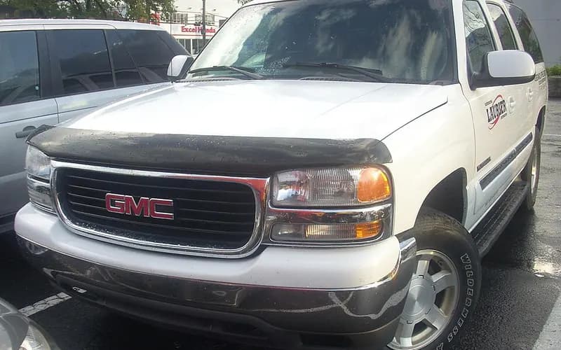
GMC Yukon XL 2000–2006
Common on this vehicle:Gauge or instrument faultWarning lightCorrosion or rustNoiseLeakReduced brakingStalls or shuts offLoss of engine power, no acceleration
Record by record
1830 records state a cause or a remedy. Each record is shown as short labels in the order fault → finding the cause → correction. Press a label to narrow to the records that state it.
Component named as the cause
Work done
How it is said to have ended
- says it was fixed12
- says it held for a while16
- says it came back34
- says it did not fix it46
- result not stated166
A ribbon is as wide as the records that state both of its ends (only the commonest are drawn). A record that names several symptoms or components runs through each. Orange is records that say the fault came back or was not fixed. Results come from owners’ reports only; one that does not say is “result not stated”. None of this is a likelihood of a cause or a rate at which work succeeds.
Read the records one by one (36)
Known issuesHydro-boost brake assist and power steering share one hydraulic supply (four campaigns)4
Recall2004–2005 GMC YUKON XL ・ 2005-08-02
Bosch Hydro-Boost Brake Accumulator Crack Recall
1Fault
- The hydraulic brake booster's pressure accumulator may crack and/or separate from the Hydro-Boost assembly in normal operation; if it separates with the hood open, fragments could injure people nearby.
- The crack or fractured surface could let hydraulic fluid leak from the accumulator circuit of the booster, and the loss of fluid would increase steering and braking effort.
2Finding the cause
Possible causes
- The over-pressurization comes from a two-function valve (TFV) that does not open within its specified limits while the hydraulic fluid in the accumulator circuit expands as the booster is exposed to rising under-hood temperatures.
Steps to confirm (in the document’s order)
- With the engine OFF, make at least five (5) high effort brake applies until the pedal feels hard.
- Turn the steering wheel to the steering lock (fully turned) position, hold for 1 to 2 seconds, then release; do this a total of 3 times.
- Install the inlet port adapter, CH 47950-2, into the booster supply port and slowly tighten it with a torque wrench to 16 N·m (12 lb ft).
- Install the accumulator pressure clamp, CH 47950-1, by sliding it over the accumulator so that it straddles the hydro-boost housing.
- If fluid comes out of the inlet port adapter at up to 65 N·m (48 lb ft) maximum torque on the clamp bolt, the hydro-boost booster assembly is OK.
3Correction
Repair
- If no fluid is seen, complete Steps 19-27 and repeat Steps 1-18; if no fluid is visible in the second evaluation, replace the hydro-boost unit.
- After the test, reinstall the supply hose/tube to the booster and tighten to 28 N·m (21 lb ft).
- When the booster is replaced, install the 4 booster to bulkhead nuts and tighten them to 36 N·m (26 lb ft).
Caution
- The inspection uses the Hydro-Boost Checking Tool, CH 47950, shipped to each dealer.
- After starting the engine, do not depress the brake pedal until instructed.
- Incorrect installation of the fixture washer will damage the accumulator end.
Read the sentences of the record
From the manufacturer’s document
- Applies to:The recall covers certain 2004 Chevrolet Kodiak and GMC TopKick; 2004-2005 Chevrolet Avalanche, Express, Silverado, Suburban; GMC Savana, Sierra, Yukon XL; and HUMMER H2 vehicles built within the listed VIN breakpoints.
- Applies to:GM limited the recall to dealer stock vehicles and sold vehicles with less than 150 days in service.
- Condition:The hydraulic brake booster's pressure accumulator may crack and/or separate from the Hydro-Boost assembly in normal operation; if it separates with the hood open, fragments could injure people nearby.
- Condition:The crack or fractured surface could let hydraulic fluid leak from the accumulator circuit of the booster, and the loss of fluid would increase steering and braking effort.
- Cause:The over-pressurization comes from a two-function valve (TFV) that does not open within its specified limits while the hydraulic fluid in the accumulator circuit expands as the booster is exposed to rising under-hood temperatures.
- Caution:The inspection uses the Hydro-Boost Checking Tool, CH 47950, shipped to each dealer.
- Confirm:With the engine OFF, make at least five (5) high effort brake applies until the pedal feels hard.
- Caution:After starting the engine, do not depress the brake pedal until instructed.
- Confirm:Turn the steering wheel to the steering lock (fully turned) position, hold for 1 to 2 seconds, then release; do this a total of 3 times.
- Confirm:Install the inlet port adapter, CH 47950-2, into the booster supply port and slowly tighten it with a torque wrench to 16 N·m (12 lb ft).
- Confirm:Install the accumulator pressure clamp, CH 47950-1, by sliding it over the accumulator so that it straddles the hydro-boost housing.
- Caution:Incorrect installation of the fixture washer will damage the accumulator end.
- Confirm:If fluid comes out of the inlet port adapter at up to 65 N·m (48 lb ft) maximum torque on the clamp bolt, the hydro-boost booster assembly is OK.
- Repair:If no fluid is seen, complete Steps 19-27 and repeat Steps 1-18; if no fluid is visible in the second evaluation, replace the hydro-boost unit.
- Repair:After the test, reinstall the supply hose/tube to the booster and tighten to 28 N·m (21 lb ft).
- Repair:When the booster is replaced, install the 4 booster to bulkhead nuts and tighten them to 36 N·m (26 lb ft).
- Cause
- CERTAIN TRUCKS, SPORT UTILITY VEHICLES, AND VANS EQUIPPED WITH BOSCH HYDRO-BOOST BRAKE ASSEMBLIES, THE HYDRAULIC BRAKE BOOSTER PRESSURE ACCUMULATOR MAY CRACK AND SEPARATE FROM THE HYDRO-BOOST ASSEMBLY DURING NORMAL OPERATING CONDITIONS.
- Remedy
- DEALERS WILL TEST THE HYDRO-BOOST ASSEMBLY FOR FUNCTIONAL OPERATION OF THE TWO-FUNCTION VALVE. IF THE HYDRO-BOOST ASSEMBLY FAILS THE TEST, DEALERS WILL REPLACE THE ASSEMBLY FREE OF CHARGE. THE RECALL BEGAN ON MARCH 23, 2005. OWNERS MAY CONTACT CHEVROLET AT 1-800-630-2438, GMC TRUCKS AT 1-866-996-9463 AND HUMMER AT 1-800-732-5493.
- Consequence
- IF A SEPARATION OCCURRED AND THE HOOD OF THE VEHICLE WERE OPEN, FRAGMENTS FROM THE ACCUMULATOR COULD CAUSE INJURY TO PEOPLE IN THE IMMEDIATE AREA. THE PRESENCE OF THIS CRACK OR FRACTURED SURFACE COULD ALLOW THE HYDRAULIC FLUID TO LEAK FROM THE ACCUMULATOR CIRCUIT OF THE BOOSTER ASSEMBLY. THE LOSS OF FLUID WOULD CAUSE INCREASED STEERING AND BRAKING EFFORT AND A CRASH MAY OCCUR WITHOUT PRIOR WARNING.
Recall2000 GMC YUKON XL ・ 2005-07-01
Hydraulic Pump Driveshaft Fracture Recall
1Fault
- The driveshaft in the power steering hydraulic pump can fracture, which results in loss of hydraulic power assist for steering.
- On vehicles with Hydro-Boost power brakes the same condition can also remove power assist for braking; an inoperative pump raises steering effort, and braking effort on Hydro-Boost vehicles, but the vehicle can still be steered and slowed.
2Finding the cause
Possible causes
- The pump supplier, Delphi-Saginaw Plant 3, had salvaged 45,000 rejected pump rotors by manually regrinding them from oversize dimensions to a thickness within tolerance.
3Correction
Repair
- Dealers are to replace the power steering hydraulic pump.
- On EVO equipped pumps, lubricate the new o-ring seal taken from the replacement pump fitting with clean power steering fluid and install it in the correct groove in the EVO actuator.
- Tighten the EVO actuator assembly to 50 N·m (37 lb ft).
- Install the front mounting bolts and tighten them to 50 N·m (37 lb ft).
- Install the rear mounting nuts to the studs and tighten them to 50 N·m (37 lb ft).
Parts
- Pumps for CK models: 88963602 (CK w/L31/JB7 Pwr Brk Sys), 88963606 (CK w/JB8/JD7 Hydr Brk Sys), 88963609 (CK w/JF9 4-Whl Disc Brk Sys) and 26081016 (CK w/JH6 Hydr Brk Sys), 1 per vehicle.
- Hydraulic power steering fluid, 89021184 (U.S.) or 89021186 (Canada), as required.
Part numbers printed in the document
88963602Look up at RockAuto (aftermarket candidates) ↗Search the web ↗
88963606Look up at RockAuto (aftermarket candidates) ↗Search the web ↗
88963609Look up at RockAuto (aftermarket candidates) ↗Search the web ↗
26081016Look up at RockAuto (aftermarket candidates) ↗Search the web ↗
89021184Look up at RockAuto (aftermarket candidates) ↗Search the web ↗
89021186Look up at RockAuto (aftermarket candidates) ↗Search the web ↗
The numbers are as the document prints them. The name and the replacing number are what the pages of GMPartsGiant, a reseller of genuine parts and not GM, state. Aftermarket equivalents are not checked here (the links only search by number). Confirm the fit for the vehicle (VIN) before ordering.
Caution
- Tools required for the CK procedure: J 25034-C pulley remover, J 25033-C pulley installer, J 43485 bleeder adapter and J 35555 Metal Mityvac.
Read the sentences of the record
From the manufacturer’s document
- Applies to:The program covers certain 2000 model year 2500/3500 Series Chevrolet CK, Silverado, Suburban and Express and GMC Sierra, Yukon XL and Savana vehicles built within the listed VIN breakpoints.
- Applies to:The defect notice names certain 2000 model year series 2500 and 3500 vehicles manufactured from May 1, 1999 through October 14, 1999.
- Condition:The driveshaft in the power steering hydraulic pump can fracture, which results in loss of hydraulic power assist for steering.
- Condition:On vehicles with Hydro-Boost power brakes the same condition can also remove power assist for braking; an inoperative pump raises steering effort, and braking effort on Hydro-Boost vehicles, but the vehicle can still be steered and slowed.
- Cause:The pump supplier, Delphi-Saginaw Plant 3, had salvaged 45,000 rejected pump rotors by manually regrinding them from oversize dimensions to a thickness within tolerance.
- Repair:Dealers are to replace the power steering hydraulic pump.
- Parts:Pumps for CK models: 88963602 (CK w/L31/JB7 Pwr Brk Sys), 88963606 (CK w/JB8/JD7 Hydr Brk Sys), 88963609 (CK w/JF9 4-Whl Disc Brk Sys) and 26081016 (CK w/JH6 Hydr Brk Sys), 1 per vehicle.
- Parts:Hydraulic power steering fluid, 89021184 (U.S.) or 89021186 (Canada), as required.
- Caution:Tools required for the CK procedure: J 25034-C pulley remover, J 25033-C pulley installer, J 43485 bleeder adapter and J 35555 Metal Mityvac.
- Repair:On EVO equipped pumps, lubricate the new o-ring seal taken from the replacement pump fitting with clean power steering fluid and install it in the correct groove in the EVO actuator.
- Repair:Tighten the EVO actuator assembly to 50 N·m (37 lb ft).
- Repair:Install the front mounting bolts and tighten them to 50 N·m (37 lb ft).
- Repair:Install the rear mounting nuts to the studs and tighten them to 50 N·m (37 lb ft).
- Repair:Install the pulley flush with 0.5 mm (0.020 in) play.
- Repair:To bleed the system, apply a vacuum of 68 kPa (20 in Hg) maximum at the pump reservoir filler neck and wait 1 minute.
- Repair:Start the engine, let it idle, and turn the steering wheel 180-360 degrees in both directions 5 times.
- Cause
- SOME PICKUP TRUCKS, VANS, AND SPORT UTILITY VEHICLES EQUIPPED WITH A HYDRAULIC PUMP DRIVESHAFT THAT CAN FRACTURE, RESULTING IN IMMEDIATE LOSS OF HYDRAULIC POWER STEERING ASSIST. ON CERTAIN VEHICLES EQUIPPED WITH HYDRO-BOOST POWER BRAKES, THE SAME CONDITION CAN RESULT IN LOSS OF POWER ASSIST FOR BRAKING AFTER THE RESERVE PRESSURE IS DEPLETED.
- Remedy
- DEALERS WILL REPLACE THE HYDRAULIC PUMP. THE CAMPAIGN BEGAN ON FEBRUARY 14, 2005. OWNERS MAY CONTACT CHEVROLET AT 1-800-630-2438 OR GMC AT 1-866-996-9463.
- Consequence
- AN INOPERATIVE PUMP CAN CAUSE INCREASED STEERING EFFORT, AND IN HYDRO-BOOST EQUIPPED VEHICLES ALSO INCREASED BRAKING EFFORT, BUT DOES NOT COMPLETELY ELIMINATE THE ABILITY TO STEER OR SLOW THE VEHICLE.
Recall2003–2004 GMC YUKON XL ・ 2004-04-02
Brake Hydro-Boost Housing Relief Valve Bore Recall
1Fault
- The relief valve bore in the brake hydro-boost module may be out of specification, which could fracture the relief valve o-ring seal inside the module.
- If the seal fractures, the driver may hear during braking an engine compartment noise like the one made when the steering wheel is turned to a full stop, and may feel slightly higher steering effort while braking and parking.
- Under certain driving conditions a fractured seal may require slightly more brake pedal effort for the same deceleration, which could result in a crash without prior warning.
2Finding the cause
Possible causes
- Inspection found a machining error in the relief bore cavity of modules produced on one of the automated boring machines used for the base housing.
Steps to confirm (in the document’s order)
- Look at the color of the relief valve: if it is metallic yellow or looks like brass, no further action is required.
- If a yellow, pink or white paint mark is visible, no further inspection or repair is required, and any stamped number is to be disregarded.
- With no paint marks and a stamped number 2, 3 or 4 visible, no further inspection or repair is required.
- If a stamped number 1 is visible on the machined surface, the relief valve must be replaced.
3Correction
Repair
- With the ignition OFF, pump the brake pedal at least ten times.
- Unscrew the original relief valve from the hydraulic brake booster with the tool supplied with the new relief valve.
- Insert the new relief valve into the bore and tighten it to 17 N·m (13 lb ft).
- With the master cylinder mounted flush to the booster, install the nuts and tighten them to 33 N·m (24 lb ft).
Parts
- Part number 10398682, VALVE KIT, P/B BOOS CONT, quantity 1 per vehicle if required.
Part numbers printed in the document
The numbers are as the document prints them. The name and the replacing number are what the pages of GMPartsGiant, a reseller of genuine parts and not GM, state. Aftermarket equivalents are not checked here (the links only search by number). Confirm the fit for the vehicle (VIN) before ordering.
Caution
- Take care when working around the accumulator, which contains high-pressure compressed gas and hydraulic fluid.
- Do not blow compressed air into the bore or flush the valve bore with commercially available cleaners; this could damage the booster or master cylinder.
Read the sentences of the record
From the manufacturer’s document
- Applies to:The recall covers certain 2003 and 2004 model year Cadillac Escalade, Escalade EXT and Escalade ESV; Chevrolet Silverado, Avalanche, Suburban and Express; GMC Sierra, Yukon, Yukon XL and Savana; HUMMER H2; and 2004 model year Chevrolet Tahoe vehicles built within the listed VIN breakpoints.
- Condition:The relief valve bore in the brake hydro-boost module may be out of specification, which could fracture the relief valve o-ring seal inside the module.
- Condition:If the seal fractures, the driver may hear during braking an engine compartment noise like the one made when the steering wheel is turned to a full stop, and may feel slightly higher steering effort while braking and parking.
- Condition:Under certain driving conditions a fractured seal may require slightly more brake pedal effort for the same deceleration, which could result in a crash without prior warning.
- Cause:Inspection found a machining error in the relief bore cavity of modules produced on one of the automated boring machines used for the base housing.
- Confirm:Look at the color of the relief valve: if it is metallic yellow or looks like brass, no further action is required.
- Confirm:If a yellow, pink or white paint mark is visible, no further inspection or repair is required, and any stamped number is to be disregarded.
- Confirm:With no paint marks and a stamped number 2, 3 or 4 visible, no further inspection or repair is required.
- Confirm:If a stamped number 1 is visible on the machined surface, the relief valve must be replaced.
- Caution:Take care when working around the accumulator, which contains high-pressure compressed gas and hydraulic fluid.
- Repair:With the ignition OFF, pump the brake pedal at least ten times.
- Repair:Unscrew the original relief valve from the hydraulic brake booster with the tool supplied with the new relief valve.
- Caution:Do not blow compressed air into the bore or flush the valve bore with commercially available cleaners; this could damage the booster or master cylinder.
- Repair:Insert the new relief valve into the bore and tighten it to 17 N·m (13 lb ft).
- Repair:With the master cylinder mounted flush to the booster, install the nuts and tighten them to 33 N·m (24 lb ft).
- Parts:Part number 10398682, VALVE KIT, P/B BOOS CONT, quantity 1 per vehicle if required.
- Cause
- CERTAIN SPORT UTILITY VEHICLES, PICKUP TRUCKS, AND PASSENGER VANS FAIL TO COMPLY WITH THE REQUIREMENTS OF FEDERAL MOTOR VEHICLE SAFETY STANDARD NO. 135, ?PASSENGER CAR BRAKE SYSTEMS.? SOME OF THESE VEHICLES WERE PRODUCED WITH AN OUT-OF-SPECIFICATION BRAKE HYDRO-BOOST HOUSING RELIEF VALVE BORE.
- Remedy
- DEALERS ARE TO REPLACE THE HYDRO-BOOST RELIEF VALVE. THE RECALL BEGAN ON JUNE 18, 2004. OWNERS SHOULD CONTACT CADILLAC AT 1-866-982-2339; CHEVROLET AT 1-800-630-2438; GMC AT 1-866-996-9463; OR HUMMER AT 1-866-486-6376.
- Consequence
- CONSEQUENTLY, THE VALVE O-RING SEAL MAY FRACTURE. STEERING EFFORTS MAY BE SLIGHTLY INCREASED WHILE BRAKING OR PARKING. UNDER CERTAIN DRIVING CONDITIONS, A FRACTURED SEAL MAY REQUIRE A SLIGHT INCREASE IN THE APPLIED BRAKE PEDAL EFFORT TO ACHIEVE THE SAME VEHICLE DECELERATION RATE AS PRIOR TO THE SEAT FRACTURE.
Recall2004–2005 GMC YUKON XL ・ 2005-02-15
Hydraulic Brake Booster Pressure Accumulator Crack Recall
1Fault
2Finding the cause
3Correction
Not stated
What the documents say to do
Hydro-boost brake assist and power steering share one hydraulic supply (four campaigns)Confirm
- Perform the "Power Steering System Test" found in SI and make any necessary repairs based on system diagnosis.
Repair
- Dealers replace the hydro-boost relief valve.
- Dealers test the hydro-boost assembly for functional operation and replace it if it fails.
Caution
- An inoperative pump raises steering and braking effort but does not completely remove the ability to steer or slow the vehicle.
Read the sentences of the record
- Cause
- On certain vehicles, the hydraulic brake booster's pressure accumulator may crack and/or separate from the Hydro-Boost assembly during normal vehicle operating conditions. If a separation occurred and the hood of the vehicle was open, fragments from the accumulator could cause injury to people in the immediate area. In addition, the presence of this crack or fractured surface could allow the hydraulic fluid to leak from the accumulator circuit of the booster assembly. The loss of fluid would cause increased steering and braking effort. Correction: Dealers will test and, if necessary, replace the Hydro-Boost assembly.
Known issuesUnwanted ABS activation at low speed (front wheel speed sensor mounting corrosion)2
Recall2000–2002 GMC YUKON XL ・ —
ABS activation recall in pickup trucks and SUVs
1Fault
- Corrosion may occur between the front hub/bearing assembly and the wheel speed sensor; if the brakes are applied at a speed greater than 6 km/h (3.7 mph) but less than 16 km/h (10 mph), the corrosion may cause an unwanted ABS activation.
- If this occurred where stopping distance is limited, a crash could occur.
- The condition does not set any ABS codes and does not illuminate the ABS warning lamp.
2Finding the cause
Steps to confirm (in the document’s order)
- Check the mounting surface on the sensor head for flatness against a metal machinist's scale or other straight edge, in multiple positions/directions (minimum 3).
- With the bearing rotated at about one revolution per second, the reading should be at least 350 ACmV; if it is less than 350 ACmV the wheel speed sensor must be replaced.
3Correction
Repair
- If the mounting surface on the sensor is warped or bent, the sensor must be replaced.
- Thoroughly clean the wheel speed sensor mounting surface on the bearing hub with a wire brush, sandpaper, emery cloth, scotch brite or equivalent to remove any rust or corrosion.
- Spray two thin coats of the specified rust penetrating lubricant (corrosion inhibitor) on the complete sensor mounting surface on the bearing hub, letting it dry between coats.
- When the corrosion inhibitor is dry to the touch (about 10 minutes), apply a light coating of the specified grease to the complete sensor mounting surface on the bearing hub and to the sensor and O-ring.
- Tighten the wheel speed sensor mounting bolt to 18 N·m (13 lb ft).
Parts
- Parts listed: 89022217 Lubricant, Rust Penetrating, and 01051344 Lubricant, Wheel Bearing.
Part numbers printed in the document
89022217Look up at RockAuto (aftermarket candidates) ↗Search the web ↗
01051344Look up at RockAuto (aftermarket candidates) ↗Search the web ↗
The numbers are as the document prints them. The name and the replacing number are what the pages of GMPartsGiant, a reseller of genuine parts and not GM, state. Aftermarket equivalents are not checked here (the links only search by number). Confirm the fit for the vehicle (VIN) before ordering.
Caution
- Remove the sensor by pulling it straight out of the bore; do not pry it with a screwdriver or other device, because prying will break the sensor body off in the bore.
- This revision changes some breakpoints and adds vehicles that have moved into the severe corrosion areas; copies of bulletin 05068B, issued April 2006, are to be discarded.
Read the sentences of the record
From the manufacturer’s document
- Applies to:Applies to certain 1999-2002 Chevrolet Silverado and GMC Sierra, 2000-2002 Chevrolet Tahoe, Suburban and GMC Yukon, Yukon XL, and 2002 Chevrolet Avalanche that have at any time been registered in the listed areas.
- Applies to:The revised defect notice adds Delaware, Iowa, Maryland, Minnesota, Missouri, Wisconsin and the District of Columbia to the original states of Connecticut, Illinois, Indiana, Maine, Massachusetts, Michigan, New Hampshire, New Jersey, New York, Ohio, Pennsylvania, Rhode Island, Vermont and West Virginia.
- Condition:Corrosion may occur between the front hub/bearing assembly and the wheel speed sensor; if the brakes are applied at a speed greater than 6 km/h (3.7 mph) but less than 16 km/h (10 mph), the corrosion may cause an unwanted ABS activation.
- Condition:If this occurred where stopping distance is limited, a crash could occur.
- Condition:The condition does not set any ABS codes and does not illuminate the ABS warning lamp.
- Caution:Remove the sensor by pulling it straight out of the bore; do not pry it with a screwdriver or other device, because prying will break the sensor body off in the bore.
- Confirm:Check the mounting surface on the sensor head for flatness against a metal machinist's scale or other straight edge, in multiple positions/directions (minimum 3).
- Repair:If the mounting surface on the sensor is warped or bent, the sensor must be replaced.
- Repair:Thoroughly clean the wheel speed sensor mounting surface on the bearing hub with a wire brush, sandpaper, emery cloth, scotch brite or equivalent to remove any rust or corrosion.
- Repair:Spray two thin coats of the specified rust penetrating lubricant (corrosion inhibitor) on the complete sensor mounting surface on the bearing hub, letting it dry between coats.
- Repair:When the corrosion inhibitor is dry to the touch (about 10 minutes), apply a light coating of the specified grease to the complete sensor mounting surface on the bearing hub and to the sensor and O-ring.
- Repair:Tighten the wheel speed sensor mounting bolt to 18 N·m (13 lb ft).
- Confirm:With the bearing rotated at about one revolution per second, the reading should be at least 350 ACmV; if it is less than 350 ACmV the wheel speed sensor must be replaced.
- Repair:Tighten the brake caliper mounting bracket bolts to 175 N·m (129 lb ft) on 1500 Series vehicles and 300 N·m (221 lb ft) on 2500 Series vehicles.
- Parts:Parts listed: 89022217 Lubricant, Rust Penetrating, and 01051344 Lubricant, Wheel Bearing.
- Caution:This revision changes some breakpoints and adds vehicles that have moved into the severe corrosion areas; copies of bulletin 05068B, issued April 2006, are to be discarded.
- Cause
- CERTAIN PICKUP TRUCKS AND SPORT UTILITY VEHICLES MAY EXPERIENCE UNWANTED ANTILOCK BRAKE SYSTEM (ABS) ACTIVATION. THIS CONDITION IS MORE LIKELY TO OCCUR IN ENVIRONMENTALLY CORROSIVE AREAS. THIS RECALL WILL BE LAUNCHED IN THE "SALT BELT" STATES OF CONNECTICUT, DELAWARE, ILLINOIS, INDIANA, IOWA, MARYLAND, MASSACHUSETTS, MAINE, MICHIGAN, MINNESOTA, MISSOURI, NEW HAMPSHIRE, NEW JERSEY, NEW YORK, OHIO, PENNSYLVANIA, RHODE ISLAND, VERMONT, WEST VIRGINIA, WISCONSIN AND THE DISTRICT OF COLUMBIA ONLY.
- Remedy
- DEALERS ARE TO REMOVE THE WHEEL SPEED SENSOR AND THOROUGHLY CLEAN THE WHEEL SPEED SENSOR MOUNTING SURFACE ON THE BEARING, APPLY RUST INHIBITOR TO THE CLEANED SURFACE, GREASE THE MOUNTING SURFACE, REINSTALL THE WHEEL SPEED SENSOR, AND CHECK THE PEAK-TO-PEAK OUTPUT VOLTAGE TO ENSURE THE WHEEL SPEED SIGNAL IS WITHIN SPECIFICATIONS. THE RECALL BEGAN SEPTEMBER 22, 2005. OWNERS MAY CONTACT CHEVROLET AT 1-800-630-2438 OR GMC AT 1-866-996-9463.
- Consequence
- THIS CAN CAUSE INCREASED STOPPING DISTANCES DURING LOW-SPEED BRAKE APPLICATIONS, WHICH COULD RESULT IN A CRASH.
Recall2000–2002 GMC YUKON XL ・ 2004-11-05
ABS activation at low speeds in Canadian Atlantic provinces
1Fault
2Finding the cause
3Correction
Not stated
What the documents say to do
Unwanted ABS activation at low speed (front wheel speed sensor mounting corrosion)Confirm
- The reading should be at least 350 mV AC; if it is less, the wheel speed sensor must be replaced.
Repair
- Dealers remove the sensor, clean its mounting surface on the bearing, apply rust inhibitor and grease, reinstall it and check peak-to-peak output voltage.
- The passage heading states that the repair is cleaning the wheel speed sensor mounting surface.
Caution
- Do not pry the sensor out of the bore; prying breaks the sensor body off in the bore.
Read the sentences of the record
- Cause
- Certain vehicles located in Ontario, Quebec, New Brunswick, Nova Scotia, Prince Edward Island, and Newfoundland & Labrador may experience unwanted Antilock Brake System (ABS) activation and increased stopping distances during low-speed brake application (less than 16 km/h and greater than 6 km/h). This condition does not set any ABS codes nor does it illuminate the ABS warning lamp. Correction: Dealers will remove the wheel speed sensor and thoroughly clean the wheel speed sensor mounting surface on the bearing, apply Zinc-X to the cleaned surface, grease the mounting surface, reinstall the wheel speed sensor, and check the output voltage to ensure the wheel speed signal is within specifications.
Known issuesAir bag sensing diagnostic module (SDM) anomaly - recall 02V-1782
Recall2000 GMC YUKON XL ・ 2002-01-07
1Fault
Not stated
2Finding the cause
3Correction
Read the sentences of the record
- Cause
- ON CERTAIN PICKUP AND UTILITY TRUCKS, SOME OF THESE VEHICLES HAVE AN AIR BAG SENSING DIAGNOSTIC MODULE (SDM) WHICH CONTAINS AN ANOMALY THAT COULD RESULT IN THE DRIVER AND PASSENGER'S AIR BAG FAILING TO DEPLOY DURING CERTAIN FRONTAL CRASHES.
- Remedy
- DEALERS WILL RECALIBRATE THE SDM ON THE AFFECTED VEHICLES. OWNER NOTIFICATION BEGAN AUGUST 28, 2002. OWNERS WHO TAKE THEIR VEHICLES TO AN AUTHORIZED DEALER ON AN AGREED UPON SERVICE DATE AND DO NOT RECEIVE THE FREE REMEDY WITHIN A REASONABLE TIME SHOULD CONTACT CHEVROLET AT 1-800-222-1020 OR GMC AT 1-800-462-8782.
- Consequence
- IN A VEHICLE CRASH, FRONT SEAT OCCUPANTS MAY RECEIVE MORE SEVERE INJURIES.
Recall2000 GMC YUKON XL ・ 2002-06-28
Air Bag Sensing Diagnostic Module Recalibration Recall
1Fault
Not stated
2Finding the cause
3Correction
Not stated
What the documents say to do
Air bag sensing diagnostic module (SDM) anomaly - recall 02V-178Repair
- Dealers recalibrate the SDM.
Read the sentences of the record
- Cause
- Certain vehicles have an air bag sensing diagnostic module (SDM) which contains an anomaly that could result in the driver and passenger's air bag failing to deploy during certain frontal collisions. In a vehicle crash, front seat occupants may receive more severe injuries. Correction: Dealers will recalibrate the SDM.
Known issuesEngine fuel rail crossover tube retainer screws may break (5.3L RPO L59) - recall 04V-3762
Recall2005 GMC YUKON XL ・ 2004-02-08
Engine Fuel Rail Crossover Tube Retainer Screws
1Fault
- The engine fuel rail crossover tube retainer screws were not made to specification and may break; if one breaks, fuel could leak from the crossover joint, the engine may stall, and with an ignition source an engine compartment fire could occur.
2Finding the cause
Possible causes
- The failed screw was harder than specification; the over-hardening came from a conveyor in an induction hardening operation at the fastener plant stopping or slowing excessively, exposing the screws to the hardening for too long.
Steps to confirm (in the document’s order)
- Inspect for blue or green paint dots on the fuel rail crossover tube assembly or on the throttle body; if there are any, go to step 13.
3Correction
Repair
- Hold the fuel crossover tube retainer to the bracket on the fuel rail with locking pliers, using enough force to keep the retainer from moving without damaging any parts.
- Remove the fuel rail crossover tube bracket retainer screw on one side and dispose of it properly.
- Take the new screws out of the retainer kit (P/N 89017590) and discard the retainer brackets left in the kit.
- Start the new screw by hand for at least 3 full turns into the fuel rail crossover tube retainer bracket.
- Torque the screw to 4.8Nm (42 lb in).
3 more pointsPart numbers printed in the document
The numbers are as the document prints them. The name and the replacing number are what the pages of GMPartsGiant, a reseller of genuine parts and not GM, state. Aftermarket equivalents are not checked here (the links only search by number). Confirm the fit for the vehicle (VIN) before ordering.
Parts
- Part number 89017590, RETAINER KIT, F/INJN FUEL RL C/OVR TUBE, quantity 1 per vehicle.
Part numbers printed in the document
The numbers are as the document prints them. The name and the replacing number are what the pages of GMPartsGiant, a reseller of genuine parts and not GM, state. Aftermarket equivalents are not checked here (the links only search by number). Confirm the fit for the vehicle (VIN) before ordering.
Caution
- Do not remove the crossover tube from the fuel rail or disturb the o-ring seal, because a fuel leak may result.
- The service procedure in this recall differs from the one in the service manual.
Read the sentences of the record
From the manufacturer’s document
- Applies to:The recall covers certain 2005 Chevrolet Silverado, Tahoe and Suburban and GMC Sierra, Yukon and Yukon XL vehicles equipped with a 5.3L (RPO L59) E85 V8 engine and built within the listed VIN breakpoints.
- Condition:The engine fuel rail crossover tube retainer screws were not made to specification and may break; if one breaks, fuel could leak from the crossover joint, the engine may stall, and with an ignition source an engine compartment fire could occur.
- Cause:The failed screw was harder than specification; the over-hardening came from a conveyor in an induction hardening operation at the fastener plant stopping or slowing excessively, exposing the screws to the hardening for too long.
- Confirm:Inspect for blue or green paint dots on the fuel rail crossover tube assembly or on the throttle body; if there are any, go to step 13.
- Caution:Do not remove the crossover tube from the fuel rail or disturb the o-ring seal, because a fuel leak may result.
- Caution:The service procedure in this recall differs from the one in the service manual.
- Repair:Hold the fuel crossover tube retainer to the bracket on the fuel rail with locking pliers, using enough force to keep the retainer from moving without damaging any parts.
- Repair:Remove the fuel rail crossover tube bracket retainer screw on one side and dispose of it properly.
- Parts:Part number 89017590, RETAINER KIT, F/INJN FUEL RL C/OVR TUBE, quantity 1 per vehicle.
- Repair:Take the new screws out of the retainer kit (P/N 89017590) and discard the retainer brackets left in the kit.
- Repair:Start the new screw by hand for at least 3 full turns into the fuel rail crossover tube retainer bracket.
- Repair:Torque the screw to 4.8Nm (42 lb in).
- Repair:Check that the retainer is seated and not loose by trying to wiggle it slightly; it should not move. Then re-torque the screw to 4.8Nm (42 lb in).
- Repair:Repeat steps 5 through 10 on the other side of the crossover tube.
- Repair:Check for leaks: ignition ON with the engine OFF for 2 seconds, ignition OFF for 10 seconds, ignition ON with the engine OFF, then visually inspect for fuel leaks.
- Cause
- ON CERTAIN SPORT UTILITY VEHICLES AND PICKUP TRUCKS EQUIPPED WITH 5.3L (RPO L59) V8 ENGINES, THE ENGINE FUEL RAIL CROSSOVER TUBE RETAINER SCREWS WERE NOT MANUFACTURED TO SPECIFICATIONS AND MAY BREAK.
- Remedy
- DEALERS WILL INSPECT THE FUEL RAIL CROSSOVER TUBE AND, IF NECESSARY, REPLACE THE RETAINER SCREWS. OWNERS WERE NOTIFIED BY TELEPHONE ON JULY 30, 2004, WITH A FOLLOWUP OWNER LETTER BEGAN AUGUST 5, 2004. OWNERS SHOULD CONTACT CHEVROLET AT 1-800-630-2438 OR GMC AT 1-866-996-9463. NOTE: THE GM BULLETIN LISTS THE TAHOE AND YUKON MODELS BECAUSE CANADIAN VEHICLES ARE INCLUDED IN THE BULLETIN. NO U.S. TAHOE OR YUKON VEHICLES ARE INCLUDED IN THE U.S. CAMPAIGN.
- Consequence
- IF THE TUBE RETAINER SCREW BREAKS, FUEL COULD LEAK FROM THE FUEL RAIL CROSSOVER JOINT, THE ENGINE MAY STALL AND, IF AN IGNITION SOURCE WERE PRESENT, AN ENGINE COMPARTMENT FIRE COULD OCCUR.
Recall2005 GMC YUKON XL ・ 2004-08-05
Fuel Rail Crossover Tube Retainer Screws Recall
1Fault
2Finding the cause
3Correction
Not stated
What the documents say to do
Engine fuel rail crossover tube retainer screws may break (5.3L RPO L59) - recall 04V-376Confirm
- Check for leaks: ignition ON with the engine OFF for 2 seconds, ignition OFF for 10 seconds, ignition ON with the engine OFF, then visually inspect for fuel leaks.
Repair
- Dealers inspect the fuel rail crossover tube and replace the retainer screws if necessary.
- Hold the fuel crossover tube retainer to the bracket on the fuel rail with locking pliers, using enough force to keep the retainer from moving without damaging any parts.
Caution
- The GM bulletin lists Tahoe and Yukon models because Canadian vehicles are included in the bulletin.
Read the sentences of the record
- Cause
- On certain vehicles, the fuel rail crossover tube retainer screws were not manufactured to specifications and may break. If a tube retainer screw breaks, fuel could leak from the fuel rail crossover joint, the engine may stall and, if an ignition source were present, an engine compartment fire could occur. Correction: Dealers will inspect the fuel rail crossover tube assembly and, if necessary, replace the two tube retainer screws.
Known issuesEngine fuel rail pulse damper retainer clip may fracture (8.1L V8) - recall 06V-289 / Transport Canada 20061952
Recall2004–2006 GMC YUKON XL ・ 2006-03-08
Fuel Rail Pulse Damper Retainer Clip Fracture Recall
1Fault
- The engine fuel rail pulse damper retainer clip may fracture, resulting in inadequate retention of the damper; if the damper comes loose, a fuel leak may result and may cause a fire if an ignition source is present.
2Finding the cause
Possible causes
- Analysis showed some clips were not properly heat treated and were more susceptible to fracture.
Steps to confirm (in the document’s order)
- To inspect for leaks, turn the ignition ON with the engine OFF for 2 seconds, turn it OFF for 10 seconds, turn it ON with the engine OFF, and inspect the fuel rail, fuel rail dampener, and fuel rail pressure cap and valve for fuel leaks.
3Correction
Repair
- Dealers are to replace the engine fuel rail pulse damper retainer clip.
- Connect the J 34730-1A fuel pressure gage to the fuel pressure valve, wrapping a shop towel around the fitting while connecting it to avoid spillage.
- Open the valve on the J 34730-1A to bleed the system pressure; to help relieve residual pressure in the fuel rail, push down on the fuel rail dampener, which should move inward approximately 2-3 mm (1/8 in) as the pressure releases.
- Push down on the fuel dampener and remove the fuel pressure dampener clip; discard the old clip.
- Push down on the fuel dampener and install the new fuel pressure dampener clip.
Parts
- Part: 12575017 Clamp-Fuel Pulse Dpnr, quantity 1 per vehicle.
Part numbers printed in the document
The numbers are as the document prints them. The name and the replacing number are what the pages of GMPartsGiant, a reseller of genuine parts and not GM, state. Aftermarket equivalents are not checked here (the links only search by number). Confirm the fit for the vehicle (VIN) before ordering.
Caution
- The service procedure in this recall is different from the service procedure in the service manual.
- If the fuel pressure is not relieved as instructed in step 8, or the dampener is not held in position while the clip is replaced, the dampener O-ring may not seat or seal properly, and a damaged or improperly seated O-ring may result in a fuel leak.
- Do not remove the fuel dampener from the fuel rail; if it is removed, a fuel dampener kit with a new O-ring must be installed.
- The bulletin was revised to add new information to the service procedure: warning statements were added along with some other minor changes.
Read the sentences of the record
From the manufacturer’s document
- Applies to:Applies to certain 2004-06 Chevrolet Silverado, Suburban, Avalanche; GMC Sierra, Yukon XL; and 2006 Chevrolet Kodiak and GMC TopKick equipped with an 8.1L V8 (RPO L18 - VIN G) engine.
- Applies to:The defect notice lists GMC Yukon XL (GMT800): 2004 model year manufactured 03/2003 to 06/2004 (967 vehicles), 2005 manufactured 06/2004 to 06/2005 (658), and 2006 manufactured 07/2005 to 01/2006 (152).
- Condition:The engine fuel rail pulse damper retainer clip may fracture, resulting in inadequate retention of the damper; if the damper comes loose, a fuel leak may result and may cause a fire if an ignition source is present.
- Cause:Analysis showed some clips were not properly heat treated and were more susceptible to fracture.
- Repair:Dealers are to replace the engine fuel rail pulse damper retainer clip.
- Parts:Part: 12575017 Clamp-Fuel Pulse Dpnr, quantity 1 per vehicle.
- Caution:The service procedure in this recall is different from the service procedure in the service manual.
- Repair:Connect the J 34730-1A fuel pressure gage to the fuel pressure valve, wrapping a shop towel around the fitting while connecting it to avoid spillage.
- Repair:Open the valve on the J 34730-1A to bleed the system pressure; to help relieve residual pressure in the fuel rail, push down on the fuel rail dampener, which should move inward approximately 2-3 mm (1/8 in) as the pressure releases.
- Caution:If the fuel pressure is not relieved as instructed in step 8, or the dampener is not held in position while the clip is replaced, the dampener O-ring may not seat or seal properly, and a damaged or improperly seated O-ring may result in a fuel leak.
- Caution:Do not remove the fuel dampener from the fuel rail; if it is removed, a fuel dampener kit with a new O-ring must be installed.
- Repair:Push down on the fuel dampener and remove the fuel pressure dampener clip; discard the old clip.
- Repair:Push down on the fuel dampener and install the new fuel pressure dampener clip.
- Confirm:To inspect for leaks, turn the ignition ON with the engine OFF for 2 seconds, turn it OFF for 10 seconds, turn it ON with the engine OFF, and inspect the fuel rail, fuel rail dampener, and fuel rail pressure cap and valve for fuel leaks.
- Repair:If a leak is present, a dampener kit with a new O-ring must be installed.
- Caution:The bulletin was revised to add new information to the service procedure: warning statements were added along with some other minor changes.
- Cause
- ON CERTAIN TRUCKS EQUIPPED WITH AN 8.1L V8 (RPO L8-VIN G) ENGINE HAVE A CONDITION IN WHICH THE ENGINE FUEL RAIL PULSE DAMPER RETAINER CLIP MAY FRACTURE RESULTING IN INADEQUATE RETENTION OF THE DAMPER.
- Remedy
- DEALERS WILL REPLACE THE ENGINE FUEL RAIL PULSE DAMPER RETAINER CLIP FREE OF CHARGE. THE RECALL BEGAN ON AUGUST 31, 2006. OWNERS MAY CONTACT CHEVROLET AT 1-800-630-2438 AND GMC TRUCKS AT 1-866-996-9463.
- Consequence
- IF THE DAMPER COMES LOOSE, A FUEL LEAK MAY RESULT. FUEL LEAKAGE, IN THE PRESENCE OF AN IGNITION SOURCE, COULD RESULT IN A FIRE.
Recall2004–2006 GMC YUKON XL ・ 2006-08-04
Engine fuel rail pulse damper retainer clip fracture recall
1Fault
2Finding the cause
3Correction
Not stated
What the documents say to do
Engine fuel rail pulse damper retainer clip may fracture (8.1L V8) - recall 06V-289 / Transport Canada 2006195Confirm
- To inspect for leaks, turn the ignition ON with the engine OFF for 2 seconds, turn it OFF for 10 seconds, turn it ON with the engine OFF, and inspect the fuel rail, fuel rail dampener, and fuel rail pressure cap and valve for fuel leaks.
Repair
- Dealers replace the engine fuel rail pulse damper retainer clip.
- Dealers replace the engine fuel rail pulse damper retainer clip.
Caution
- The service procedure in this recall is different from the service procedure in the service manual.
Read the sentences of the record
- Cause
- On certain vehicles, the engine fuel rail pulse damper retainer clip may fracture, resulting in inadequate retention of the damper. If the damper comes loose, a fuel leak may result. Fuel leakage in the presence of an ignition source could result in a fire. Correction: Dealers will replace the engine fuel rail pulse damper retainer clip.
Known issuesMid-frame cross member tear could puncture fuel tank in angled frontal impact - recall 03V-0192
Recall2003 GMC YUKON XL ・ —
Fuel Tank Shield Installation Recall
1Fault
2Finding the cause
3Correction
Read the sentences of the record
- Cause
- ON CERTAIN PICKUP TRUCKS AND SPORT UTILITY VEHICLES, VEHICLES, DURING A 30 DEGREE LEFT ANGLE FRONTAL IMPACT OF SUFFICIENT SEVERITY, A TEAR COULD DEVELOP IN THE MID-FRAME CROSS MEMBER AT ITS ATTACHMENT TO THE LEFT FRAME RAIL. IF THE MID-FRAME CROSS MEMBER TEARS DURING FRONTAL IMPACT AND PRODUCES A SHARP EDGE, CONTACT OF THE SHARP EDGE WITH THE FUEL TANK COULD RESULT IN A PUNCTURE OF THE FUEL TANK AND POSSIBLE FUEL LEAKAGE.
- Remedy
- DEALERS WILL INSTALL A FUEL TANK SHIELD. OWNER NOTIFICATION BEGAN FEBRUARY 20, 2003. OWNERS WHO TAKE THEIR VEHICLES TO AN AUTHORIZED DEALER ON AN AGREED UPON SERVICE DATE AND DO NOT RECEIVE THE FREE REMEDY WITHIN A REASONABLE TIME SHOULD CONTACT CHEVROLET AT 1-800-222-1020 OR GMC AT 1-800-462-8782.
- Consequence
- FUEL LEAKAGE, IN THE PRESENCE OF AN IGNITION SOURCE, COULD RESULT IN A FIRE.
Recall2003 GMC YUKON XL ・ 2003-01-28
2500 Series Mid-Frame Cross Member Fuel Tank Puncture Recall
1Fault
2Finding the cause
3Correction
Not stated
What the documents say to do
Mid-frame cross member tear could puncture fuel tank in angled frontal impact - recall 03V-019Repair
- Dealers install a fuel tank shield.
Read the sentences of the record
- Cause
- On certain 2500 series vehicles, a tear could develop in the mid-frame cross member at its attachment to the left frame rail during a 30 degree left angle frontal impact of sufficient severity. If the mid-frame cross member tears during frontal impact and produces a sharp edge, contact of the sharp edge with the fuel tank may result in a puncture of the fuel tank and possible fuel leakage. If a sufficient amount of fuel were to leak out and if an ignition source were present, a vehicle fire could occur. Correction: Dealer will install a fuel tank shield.
Known issuesShift lever position indicator in the instrument cluster may not illuminate (FMVSS 102) - recall 05V-0552
Recall2005 GMC YUKON XL ・ —
Automatic Transmission Shift Lever Position Indicator Illumination Recall
1Fault
- Under certain starting conditions the shift lever position indicator in the instrument panel cluster may not illuminate; on later start-ups the condition may or may not recur.
- If the indicator does not illuminate, the driver may not know which gear is selected and the vehicle may move in an unintended direction, possibly injuring people outside the vehicle.
2Finding the cause
Possible causes
- The PRNDL indicator behavior is induced only by a very specific battery voltage waveform and depends on vehicle level characteristics, while the vehicle otherwise operates normally.
- The "blank PRNDL" anomaly appeared at the assembly plants after interim 2005 model year instrument panel cluster revisions that began on January 31, 2005.
3Correction
Repair
- Dealers are to reprogram the instrument panel cluster.
- Prepare the vehicle for instrument panel cluster (IPC) reprogramming, then program the IPC using TIS data version 2.25.
Parts
- No parts are required for this recall.
Caution
- The service calibration is in Techline Information System (TIS) data version 2.25 and on TIS CD-ROM version 3.
- A later dealer message says TIS Data 2.50 has been released, so dealers no longer need to contact the Techline Customer Support Center (TCSC) for a VCI number to access the calibration.
- Vehicles with manual transmissions are not involved in this recall and need no further action.
Read the sentences of the record
From the manufacturer’s document
- Applies to:The recall covers certain 2005 Cadillac Escalade, Escalade ESV, Escalade EXT; Chevrolet Avalanche, Silverado, Suburban, Tahoe; and GMC Sierra, Yukon, Yukon XL vehicles equipped with an automatic transmission and built within the listed VIN breakpoints.
- Condition:Under certain starting conditions the shift lever position indicator in the instrument panel cluster may not illuminate; on later start-ups the condition may or may not recur.
- Condition:If the indicator does not illuminate, the driver may not know which gear is selected and the vehicle may move in an unintended direction, possibly injuring people outside the vehicle.
- Cause:The PRNDL indicator behavior is induced only by a very specific battery voltage waveform and depends on vehicle level characteristics, while the vehicle otherwise operates normally.
- Cause:The "blank PRNDL" anomaly appeared at the assembly plants after interim 2005 model year instrument panel cluster revisions that began on January 31, 2005.
- Repair:Dealers are to reprogram the instrument panel cluster.
- Repair:Prepare the vehicle for instrument panel cluster (IPC) reprogramming, then program the IPC using TIS data version 2.25.
- Caution:The service calibration is in Techline Information System (TIS) data version 2.25 and on TIS CD-ROM version 3.
- Caution:A later dealer message says TIS Data 2.50 has been released, so dealers no longer need to contact the Techline Customer Support Center (TCSC) for a VCI number to access the calibration.
- Parts:No parts are required for this recall.
- Caution:Vehicles with manual transmissions are not involved in this recall and need no further action.
- Cause
- CERTAIN SPORT UTILITY VEHICLES EQUIPPED WITH AN AUTOMATIC TRANSMISSION, FAIL TO COMPLY WITH THE REQUIREMENTS OF FEDERAL MOTOR VEHICLE SAFETY STANDARD NO. 102, "TRANSMISSION SHIFT LEVER SEQUENCE, STARTER INTERLOCK AND TRANSMISSION BRAKING EFFECT." UNDER CERTAIN VEHICLE STARTING CONDITIONS, THE SHIFT LEVER POSITION INDICATOR LOCATED IN THE INSTRUMENT PANEL CLUSTER MAY NOT ILLUMINATE. IF THE SHIFT LEVER POSITION INDICATOR DOES NOT ILLUMINATE, THE DRIVER MAY NOT KNOW WHICH GEAR THE VEHICLE IS IN.
- Remedy
- DEALERS WILL REPROGRAM THE INSTRUMENT PANEL CLUSTER FREE OF CHARGE. THE RECALL BEGAN ON FEBRUARY 14, 2005. OWNERS MAY CONTACT CADILLAC AT 1-866-982-2339, CHEVROLET AT 1-800-630-2438, AND GMC AT 1-866-996-9463.
- Consequence
- THE VEHICLE MAY MOVE IN AN UNINTENDED DIRECTION RESULTING IN POSSIBLE INJURY TO OTHERS OUTSIDE OF THE VEHICLE.
Recall2005 GMC YUKON XL ・ 2005-02-15
Shift Lever Position Indicator Illumination Recall
1Fault
Not stated
2Finding the cause
3Correction
Not stated
What the documents say to do
Shift lever position indicator in the instrument cluster may not illuminate (FMVSS 102) - recall 05V-055Repair
- Dealers reprogram the instrument panel cluster.
- Prepare the vehicle for instrument panel cluster (IPC) reprogramming, then program the IPC using TIS data version 2.25.
Read the sentences of the record
- Cause
- Certain vehicles equipped with an automatic transmission fail to comply with the requirements of CMVSS 101 - Location, identification and illumination of displays. Under certain vehicle starting conditions, the shift lever position indicator located in the instrument panel cluster may not illuminate. In subsequent vehicle start-ups, this condition may or may not occur again. If the shift lever position indicator does not illuminate, the driver may not know which gear the vehicle is in and the vehicle may move in an unintended direction, resulting in possible injury to others outside of the vehicle. Correction: Dealers will reprogram the instrument panel cluster.
Known issuesHVAC blower motor resistor module / connector overheating1
Recall2003–2006 GMC YUKON XL ・ 2011-02-21
HVAC Blower Motor Resistor Module Overheating
1Fault
2Finding the cause
3Correction
Not stated
What the documents say to do
HVAC blower motor resistor module / connector overheatingRepair
- Dealers install a new blower motor resistor and resistor module connector.
- Cut the wires back far enough to remove any melted insulation.
Caution
- The connector must be replaced even if it was replaced in an earlier repair.
Read the sentences of the record
- Cause
- On certain vehicles, the interface between the electrical terminals of the Heating, Ventilation, and Air Conditioning (HVAC) blower relay resistor module and the wiring connector (which powers the module) may be incapable of conducting higher current levels for sustained periods of operation. In addition, moisture and other contaminants (such as road de-icing materials) may enter the fresh air intake plenum and contact the internal circuit of the module or corrode the terminals. These conditions may cause the relay resistor module or wiring connector to overheat, causing various symptoms such as: the HVAC blower may not function on certain or all blower speed settings; a burning-plastic smell or smoke may be present in the vehicle, or; the HVAC blower may run continually with the ignition in the OFF position. These warning signs could, in certain instances, be leading indicators of an impending vehicle fire, which could result in property damage and/or personal injury. Correction: Owners will be provided with additional warranty coverage for the blower motor resistor module/wiring connector overheating condition. Under this "special warranty coverage", should this condition occur within 10 years or 240,000 km from first vehicle registration, dealers will install a replacement blower motor resistor and resistor module connector.
Known issuesBrake pedal pushrod retainer missing - recall 05V-1031
Recall2005 GMC YUKON XL ・ —
Brake Pedal Pushrod Retainer Recall 05039
1Fault
- The brake pedal pushrod retainer may be missing; without it the brake booster pushrod could disengage from the brake pedal, causing a loss of brakes and possibly a crash without prior warning.
2Finding the cause
Possible causes
- On the vehicles examined, the brake pedal clip that retains the brake pedal push rod to the brake pedal was missing.
- The second shift operator at the assembly plant did not follow the standardized work instruction, so the clip was not always installed; only vehicles built on the second shift were found with clips missing.
Steps to confirm (in the document’s order)
- Inspect for the presence and proper installation of the brake pushrod retaining clip.
3Correction
Repair
- Install a new clip if necessary.
Parts
- Very few vehicles are expected to need a brake pedal pushrod retainer; if one is needed, it is ordered on a CSO (Customer Special Order). No part number is printed.
Caution
- Confirm vehicle eligibility through GMVIS before starting recall repairs; not all vehicles within the breakpoints may be involved.
Read the sentences of the record
From the manufacturer’s document
- Applies to:The recall covers certain 2005 Chevrolet Suburban and Tahoe and GMC Yukon and Yukon XL vehicles built within the listed VIN breakpoints.
- Applies to:VIN breakpoints: 2005 GMC Yukon from 5J206278 through 5J218221; 2005 GMC Yukon XL from 5J215251 through 5J218187.
- Caution:Confirm vehicle eligibility through GMVIS before starting recall repairs; not all vehicles within the breakpoints may be involved.
- Condition:The brake pedal pushrod retainer may be missing; without it the brake booster pushrod could disengage from the brake pedal, causing a loss of brakes and possibly a crash without prior warning.
- Cause:On the vehicles examined, the brake pedal clip that retains the brake pedal push rod to the brake pedal was missing.
- Cause:The second shift operator at the assembly plant did not follow the standardized work instruction, so the clip was not always installed; only vehicles built on the second shift were found with clips missing.
- Confirm:Inspect for the presence and proper installation of the brake pushrod retaining clip.
- Repair:Install a new clip if necessary.
- Parts:Very few vehicles are expected to need a brake pedal pushrod retainer; if one is needed, it is ordered on a CSO (Customer Special Order). No part number is printed.
- Cause
- ON CERTAIN SPORT UTILITY VEHICLES, THE BRAKE PEDAL PUSHROD RETAINER MAY BE MISSING. IF THE RETAINER IS MISSING, THE BRAKE BOOSTER PUSHROD COULD DISENGAGE FROM THE BRAKE PEDAL.
- Remedy
- DEALERS WILL INSPECT THE VEHICLES FOR THE BRAKE PEDAL PUSHROD RETAINER AND INSTALL ONE IF IT IS MISSING FREE OF CHARGE. THE MANUFACTURER BEGAN CONTACTING OWNERS BY TELEPHONE ON MARCH 10, 2005. OWNERS MAY CONTACT CHEVROLET AT 1-800-630-2438 OR GMC AT 1-866-996-9463.
- Consequence
- THIS COULD RESULT IN A LOSS OF BRAKES WHICH COULD RESULT IN A CRASH.
Known issuesCrankshaft position sensor may work intermittently or fail (8.1L V8) - recall 07V-5211
Recall2001 GMC YUKON XL ・ 2007-11-09
Crankshaft Position Sensor Failure Recall
1Fault
2Finding the cause
3Correction
Not stated
What the documents say to do
Crankshaft position sensor may work intermittently or fail (8.1L V8) - recall 07V-521Repair
- Dealers replace the crankshaft position sensor.
- As the remedy, an improved CKP is installed.
Caution
- All of the surveyed consumers noted multiple stalling events before the CKP was properly diagnosed and replaced.
Read the sentences of the record
- Cause
- On certain vehicles equipped with an 8.1L engine, the crankshaft position sensor may fail. If the sensor operates intermittently, the Service Engine Soon (SES) light may illuminate and the vehicle may run rough. In addition, the engine may stall, and if so, may re-start immediately or after a cool-down period. If the sensor becomes inoperable permanently, the engine will quit running and will not re-start. Engine stalling would result in lost propulsion which, in conjunction with traffic and road conditions, and the driver's reactions, could increase the risk of a crash. Correction: Dealers will replace the crankshaft position sensor.
Known issuesPositive battery cable contact with steering shaft universal joint (Denali) - Transport Canada 20010921
Recall2001 GMC YUKON XL ・ 2001-04-12
Positive battery cable fire risk recall
1Fault
2Finding the cause
3Correction
Not stated
What the documents say to do
Positive battery cable contact with steering shaft universal joint (Denali) - Transport Canada 2001092Repair
- Dealers inspect the cable routing and reroute if necessary.
- The cable is also inspected for wear and replaced if necessary.
Read the sentences of the record
- Cause
- On certain Yukon Denali and Yukon XL Denali vehicles, the positive battery cable assembly that could come in contact with the steering shaft universal joint. This could eventually cause a wear through of the cable assembly convoluted conduit and cable insulation and result in intermittent electrical shorting. This could result in overheating and igniting of the cable insulation and conduit and a possible underhood fire. Correction: Dealers will inspect the positive battery cable for proper routing and reroute if necessary. Cable will also be inspected for wear of the conduit and cable insulation, and replaced if necessary.
Known issuesAftermarket part (not the vehicle as built): Federal-Mogul National / Carquest replacement wheel hub assembly retention nut - recall 07E-1061
Recall2000–2006 GMC YUKON XL ・ —
Wheel Hub Assembly Bearing Nut Loosening Recall
1Fault
- The inboard retention nut that maintains the hub bearing assembly can loosen, resulting in an ABS light indication, noise, and/or wheel separation from the vehicle; wheel separation can result in a vehicle crash.
2Finding the cause
Steps to confirm (in the document’s order)
- On 2x4 vehicles, raise the vehicle on an approved hoist first; the hub assembly is good if a yellow, green or blue paint mark is seen on the grease cap on the inboard side of the steering knuckle.
- If the paint mark is not present, remove the wheel and the brake rotor and clean rust from the hub assembly face to check for the date code stamping.
- Defective hub assemblies can be identified by the country of origin on the package together with a recalled date code, by the date code on the package, or by the date code on the hub assembly.
- If a round yellow sticker is present on the box label, the part is good.
3Correction
Repair
- The hub assemblies were manufactured for aftermarket use; owners of these parts should have them removed and replaced as soon as possible.
- Federal-Mogul will replace the recalled hub assemblies free of charge.
Parts
- The recalled part numbers are 515020, 515021, 515025, 515053, 515054, 515059 and 515060.
Read the sentences of the record
From the manufacturer’s document
- Applies to:This is an equipment recall by Federal-Mogul of certain wheel hub assemblies sold as replacement parts only.
- Applies to:The recalled hub assemblies were packaged and sold between January 23, 2006 and December 20, 2007 under the National and CARQUEST Premium (BGS/Blue) brands, in 7 base part numbers.
- Parts:The recalled part numbers are 515020, 515021, 515025, 515053, 515054, 515059 and 515060.
- Applies to:The application lists include GMC 1500 Yukon (2WD) and GMC 1500 Yukon XL (2WD), 2001-2006.
- Applies to:ILJIN manufactured the recalled hub assemblies from December 27, 2005 to November 29, 2007.
- Condition:The inboard retention nut that maintains the hub bearing assembly can loosen, resulting in an ABS light indication, noise, and/or wheel separation from the vehicle; wheel separation can result in a vehicle crash.
- Confirm:On 2x4 vehicles, raise the vehicle on an approved hoist first; the hub assembly is good if a yellow, green or blue paint mark is seen on the grease cap on the inboard side of the steering knuckle.
- Confirm:If the paint mark is not present, remove the wheel and the brake rotor and clean rust from the hub assembly face to check for the date code stamping.
- Confirm:Defective hub assemblies can be identified by the country of origin on the package together with a recalled date code, by the date code on the package, or by the date code on the hub assembly.
- Confirm:If a round yellow sticker is present on the box label, the part is good.
- Repair:The hub assemblies were manufactured for aftermarket use; owners of these parts should have them removed and replaced as soon as possible.
- Repair:Federal-Mogul will replace the recalled hub assemblies free of charge.
- Cause
- CERTAIN FEDERAL-MOGUL REPLACEMENT WHEEL HUB ASSEMBLIES WITH THE BRAND NAMES: NATIONAL, CARQUEST P/NOS. 515020, 515021, 515025, 515053, 515054, 515059, AND 515060, SHIPPED BETWEEN JANUARY 23, 2006, AND DECEMBER 20, 2007, SOLD FOR LIGHT DUTY AND MEDIUM DUTY TRUCKS. THE INBOARD RETENTION NUT USED TO MAINTAIN HUB BEARING ASSEMBLY CAN LOOSEN RESULTING IN AN ABS LIGHT INDICATION, NOISE, AND/OR WHEEL SEPARATION.
- Remedy
- FEDERAL-MOGUL WILL NOTIFY CUSTOMERS AND WILL REPLACE THE HUB ASSEMBLY FREE OF CHARGE. THE RECALL BEGAN ON FEBRUARY 7, 2008. OWNERS CAN CONTACT FEDERAL-MOGUL TOLL-FREE AT 877-489-6659.
- Consequence
- WHEEL SEPARATION CAN RESULT IN A VEHICLE CRASH.
Known issuesFront right-hand brake pipe contact with body cross sill - recall 00V-3451
Recall2000 GMC YUKON XL ・ —
Front Right Brake Pipe Clearance Recall
1Fault
2Finding the cause
3Correction
Read the sentences of the record
- Cause
- VEHICLE DESCRIPTION: LIGHT DUTY PICKUP TRUCKS AND SPORT UTILITY VEHICLES. SOME OF THESE VEHICLES HAVE A CLEARANCE CONDITION BETWEEN THE FRONT RIGHT-HAND BRAKE PIPE AND THE BODY CROSS SILL THAT COULD DECREASE TO THE POINT OF ALLOWING CONTACT DURING THE LIFE OF THE VEHICLE. IF CONTACT OCCURS AND THE BRAKE PIPE BECOMES DAMAGED, IN HALF OF THE BRAKE SYSTEM THERE CAN BE A LOSS OF BRAKE FLUID AND PRESSURE. THE BRAKE WARNING LAMP WILL BE ACTIVATED WHEN THE BRAKE FLUID LEVEL REACHES THE INDICATOR LIMIT.
- Remedy
- DEALERS WILL INSPECT THE FRONT RIGHT-HAND BRAKE PIPE FOR WEAR. IF THERE ARE SIGNS OF WEAR, THIS SECTION OF THE BRAKE PIPE WILL BE REPLACED WITH A NEW DESIGNED BRAKE PIPE SECTION. IF THERE ARE NOT SIGNS OF WEAR ON THE BRAKE PIPE, THE DEALER WILL INSTALL A SPACER CLIP TO ENSURE SUFFICIENT CLEARANCE BETWEEN THE BRAKE PIPE AND THE BODY CROSS SILL.
- Consequence
- DURING BRAKING, THE PEDAL WILL BE LOWER THAN NORMAL AND STOPPING DISTANCES WILL BE LONGER. IF THIS OCCURS WHEN STOPPING DISTANCE IS LIMITED, A CRASH COULD OCCUR.
Known issuesFuel module reservoir assembly: fuel pump wire connectors may overheat - recall 05V-1551
Recall2000–2001 GMC YUKON XL ・ —
Fuel Module Reservoir Assembly Overheating Recall
1Fault
- Some vehicles were built with fuel module reservoir assemblies whose fuel pump wires and/or connectors may overheat under certain operating conditions.
- If the exposed ignition circuit wire shorts to ground, the fuel pump fuse blows, disabling the fuel pump and causing an engine stall or no-start; if the ignition circuit or ground wire shorts to the fuel level sender card wires, fuel level readings may be inaccurate.
- If enough heat reaches the pass-through connector, a hole may form in it, which may turn on the Service Engine Soon light during the emission system diagnostics routine; fuel vapor, and in some cases liquid fuel, may leak from the tank through the hole.
- If enough fuel leaked out and an ignition source were present, a vehicle fire could occur.
2Finding the cause
Possible causes
- Fretting corrosion caused by vibration inside the tank was identified as the cause of high resistance within the fuel pump connector.
3Correction
Repair
- Dealers remove the fuel tank, remove the fuel module reservoir assembly and install a new service kit, which includes a new pass-through connector and a wiring harness for the fuel pump and fuel sender card.
- Start by disconnecting the negative battery cable, then remove and discard the "ECM B" fuse.
- In the revised bulletin, the fuel and EVAP pipes are capped with J 41413-300, EVAP Cap/Plug Kit, to prevent fuel system contamination.
- Remove the 4 pin Metri Pack 150 electrical connector from the vehicle's body harness.
- Connect the new GT280 connector to the vehicle's body harness with the 4 butt splice connectors contained in the kit.
Parts
- Part number 15824379, Harness Kit, F/Tnk F/Pmp Mdl Wrg, quantity 1 per vehicle.
Part numbers printed in the document
15824379Harness Kit, Fuel Tank Fuel Pump Module WiringLook up at RockAuto (aftermarket candidates) ↗Search the web ↗
No successor statedas stated by GMPartsGiant (checked 2026-10-06) ↗
The numbers are as the document prints them. The name and the replacing number are what the pages of GMPartsGiant, a reseller of genuine parts and not GM, state. Aftermarket equivalents are not checked here (the links only search by number). Confirm the fit for the vehicle (VIN) before ordering.
Caution
- Do not handle the fuel sender assembly by the fuel pipes; the leverage could damage the joints.
- Always replace the fuel sender gasket when reinstalling the fuel sender assembly, to reduce the risk of fire and injury from a fuel leak.
Read the sentences of the record
From the manufacturer’s document
- Applies to:The recall covers certain 2000-2001 Chevrolet 1500 Series Suburban and GMC 1500 Series Yukon XL vehicles built within the listed VIN breakpoints.
- Condition:Some vehicles were built with fuel module reservoir assemblies whose fuel pump wires and/or connectors may overheat under certain operating conditions.
- Condition:If the exposed ignition circuit wire shorts to ground, the fuel pump fuse blows, disabling the fuel pump and causing an engine stall or no-start; if the ignition circuit or ground wire shorts to the fuel level sender card wires, fuel level readings may be inaccurate.
- Condition:If enough heat reaches the pass-through connector, a hole may form in it, which may turn on the Service Engine Soon light during the emission system diagnostics routine; fuel vapor, and in some cases liquid fuel, may leak from the tank through the hole.
- Condition:If enough fuel leaked out and an ignition source were present, a vehicle fire could occur.
- Cause:Fretting corrosion caused by vibration inside the tank was identified as the cause of high resistance within the fuel pump connector.
- Repair:Dealers remove the fuel tank, remove the fuel module reservoir assembly and install a new service kit, which includes a new pass-through connector and a wiring harness for the fuel pump and fuel sender card.
- Parts:Part number 15824379, Harness Kit, F/Tnk F/Pmp Mdl Wrg, quantity 1 per vehicle.
- Repair:Start by disconnecting the negative battery cable, then remove and discard the "ECM B" fuse.
- Repair:In the revised bulletin, the fuel and EVAP pipes are capped with J 41413-300, EVAP Cap/Plug Kit, to prevent fuel system contamination.
- Caution:Do not handle the fuel sender assembly by the fuel pipes; the leverage could damage the joints.
- Caution:Always replace the fuel sender gasket when reinstalling the fuel sender assembly, to reduce the risk of fire and injury from a fuel leak.
- Repair:Remove the 4 pin Metri Pack 150 electrical connector from the vehicle's body harness.
- Repair:Connect the new GT280 connector to the vehicle's body harness with the 4 butt splice connectors contained in the kit.
- Repair:Install the fuel tank strap attaching bolts and tighten them to 40 N·m (30 lb ft).
- Repair:Install the new fuel pump fuse contained in the kit into the vehicle's electrical center (ECM B).
- Cause
- CERTAIN TRUCKS AND SPORT UTILITY VEHICLES WERE BUILT WITH FUEL MODULE RESERVOIR ASSEMBLIES THAT CONTAIN FUEL PUMP WIRES CONNECTORS MAY OVERHEAT UNDER CERTAIN OPERATING CONDITIONS.
- Remedy
- DEALERS WILL REMOVE THE FUEL TANK, AND REMOVE THE MODULE RESERVOIR ASSEMBLIES FROM THE TANK, AND INSTALL A NEW SERVICE KIT FREE OF CHARGE. AN INTERIM LETTER TO OWNERS WAS MAILED ON MAY 25, 2005. THE OWNERS WERE RE-NOTIFIED ON OCTOBER 19, 2005, SINCE PARTS ARE NOW AVAILABE. OWNERS MAY CONTACT CHEVROLET AT 1-800-630-2438 AND GMC AT 1-866-996-9463.
- Consequence
- IF THE IGNITION CIRCUIT WIRE IS EXPOSED, THE FUEL PUMP FUSE WILL BLOW, DISABLING THE FUEL PUMP AND CAUSING AN ENGINE STALL OR NO-START CONDITION. IF SUFFICIENT HEAT IS CONDUCTED TO THE PASS-THROUGH CONNECTOR, A HOLE IN THE CONNECTOR MAY RESULT, WHICH MAY CAUSE A 'SERVICE ENGINE SOON' LIGHT TO BE ILLUMINATED DURING THE EMISSION SYSTEM DIAGNOSTIC ROUTINE. FUEL VAPOR AND IN SOME CASES LIQUID FUEL MAY LEAK OUT OF THE FUEL TANK THROUGH THE HOLE IN THE CONNECTOR BODY. FUEL LEAKAGE, IN THE PRESENCE OF AN IGNITION SOURCE, COULD RESULT IN A FIRE. ALSO IF THE IGNITION CIRCUIT OR GROUND WIRE IS EXPOSED AND SHORTS TO THE FUEL LEVEL SENDER CARD WIRES, INACCURATE FUEL LEVEL READINGS MAY RESULT.
Known issuesRear door upper hinge welds out of specification (FMVSS 214) - recall 03V-0371
Recall2003 GMC YUKON XL ・ 2003-06-02
Side impact door hinge weld inspection recall
1Fault
Not stated
2Finding the cause
3Correction
What the documents say to do
Rear door upper hinge welds out of specification (FMVSS 214) - recall 03V-037Confirm
- Dealers inspect the welds on the left rear door upper hinge.
Repair
- If a weld is out of specification, a bolt is installed to secure the hinge.
Read the sentences of the record
- Cause
- CERTAIN SPORT UTILITY VEHICLES FAIL TO COMPLY WITH REQUIREMENTS OF FEDERAL MOTOR VEHICLE SAFETY STANDARD NO. 214, "SIDE IMPACT PROTECTION." THESE VEHICLES ARE BUILT WITH FOUR WELDS ON THE REAR DOOR UPPER HINGE. ON SOME OF THESE VEHICLES, ONE OR TWO OF THE WELDS MAY NOT BE TO SPECIFICATION.
- Remedy
- DEALERS WILL INSPECT THE WELDS ON THE LEFT REAR DOOR UPPER HINGE. IF A WELD IS FOUND OUT-OF-SPECIFICATION, A BOLT WILL BE INSTALLED TO SECURE THE HINGE. OWNER NOTIFICATION BEGAN FEBRUARY 17, 2003. OWNERS WHO TAKE THEIR VEHICLES TO AN AUTHORIZED DEALER ON AN AGREED UPON SERVICE DATE AND DO NOT RECEIVE THE FREE REMEDY WITHIN A REASONABLE TIME SHOULD CONTACT CADILLAC AT 1-800-458-8006, CHEVROLET AT 1-800-222-1020, OR GMC AT 1-800-462-8782.
- Consequence
- AS A RESULT, THE DOOR STRENGTH MAY BE DEGRADED DURING A SIDE IMPACT VEHICLE CRASH.
Known issues2nd/3rd row outboard seat belt retractor internal crack - recall 01V-1591
Recall2001 GMC YUKON XL ・ —
1Fault
2Finding the cause
3Correction
Read the sentences of the record
- Cause
- VEHICLE DESCRIPTION: PICKUP AND UTILITY TRUCKS. SOME OF THESE VEHICLES HAVE AN INTERNAL COMPONENT IN THE OUTBOARD SEAT BELT RETRACTORS FOR THE 2ND AND 3RD ROW OF SEATS THAT COULD BE CRACKED. WITH REPEATED ACTUATION OF THE LOCKING MECHANISM, THE CRACK COULD SPREAD TO THE POINT SUCH THAT THE SEAT BELT WOULD NO LONGER LOCK.
- Remedy
- DEALERS WILL INSPECT THE OUTBOARD SEAT BELTS FOR SPECIFIC LOT NUMBERS AND REPLACE THE BELTS IF NECESSARY. GM IS ENCLOSING AN INSPECTION PROCEDURE FOR THE OWNERS TO USE OR THEY CAN HAVE THEIR DEALERS DO THE INSPECTIONS. OWNER NOTIFICATION BEGAN JULY 2, 2001. OWNERS WHO TAKE THEIR VEHICLES TO AN AUTHORIZED DEALER ON AN AGREED UPON SERVICE DATE AND DO NOT RECEIVE THE FREE REMEDY WITHIN A REASONABLE TIME SHOULD CONTACT CHEVROLET AT 1-800-222-1020 OR GMC AT 1-800-462-8782.
- Consequence
- IN A CRASH, INCREASED OCCUPANT INJURY COULD RESULT FROM THE NO-LOCK CONDITION.
Known issuesLoose or missing rear wheelhouse plugs (exhaust gas entry) - recall 00V-3431
Recall2000–2001 GMC YUKON XL ・ —
1Fault
Not stated
2Finding the cause
3Correction
Read the sentences of the record
- Cause
- VEHICLE DESCRIPTION: LIGHT DUTY PICKUP TRUCKS AND SPORT UTILITY VEHICLES. SOME OF THESE VEHICLES HAVE LOOSE OR MISSING REAR WHEELHOUSE PLUGS. UNDER CERTAIN VEHICLE OPERATING CONDITIONS, EXHAUST GASES CAN FLOW FORWARD AND ACCUMULATE IN THE REAR WHEELHOUSE.
- Remedy
- DEALERS WILL INSPECT THE VEHICLE FOR LOOSE OR MISSING WHEELHOUSE PLUGS AND INSTALL NEW PLUGS IF NECESSARY.
- Consequence
- THESE GASES COULD FLOW INTO THE PASSENGER COMPARTMENT IF THE PLUG IS MISSING OR LOOSE AND COULD CAUSE POSSIBLE ILLNESS, UNCONSCIOUSNESS, OR DEATH.
Known issuesTire and loading information label lists inaccurate vehicle capacity weight (FMVSS 110) - recall 05V-5521
Recall2006 GMC YUKON XL ・ 2005-07-12
Tire and Loading Information Label Inaccuracy Recall
1Fault
- The Tire and Loading Information Label shows an incorrect value for the maximum combined weight of occupants and cargo; loading to the amount shown could exceed the gross vehicle weight rating (GVWR), and continuous overloading could reduce the long-term durability of chassis components.
2Finding the cause
Possible causes
- The labels audited for the C/K full-size truck platform did not properly reflect the vehicle weight capacity with the manufacturing build variation (MBV) subtracted.
Steps to confirm (in the document’s order)
- The Tire and Loading Information Label is attached below the door lock post (striker) on the pillar.
3Correction
Repair
- Dealers install a new partial label over the existing label; the new label contains only the corrected loading information.
- Make sure the current label and the surrounding area are clean and dry, using a non-oil based cleaner, preferably isopropyl alcohol.
- Align the new label over the matching text on the current label, apply it and smooth it from the center out.
Parts
- If additional labels are required, dealers follow the bulletin's ordering instructions to determine the correct label to order.
Caution
- The bulletin states that this recall will expire May 31, 2006.
- Vehicle eligibility is to be confirmed before beginning repairs; not all vehicles within the breakpoints may be involved.
Read the sentences of the record
From the manufacturer’s document
- Applies to:Applies to certain 2006 Buick Rainier, Terraza; Cadillac Escalade, Escalade ESV, Escalade EXT; Chevrolet Avalanche, Colorado, Express, Silverado, SSR, Suburban, Tahoe, TrailBlazer, TrailBlazer EXT, Uplander; GMC Canyon, Envoy, Envoy XL, Savana, Sierra, Yukon, Yukon XL; HUMMER H2, H3; Pontiac Montana SV6; and Saturn Relay, which fail to conform to Federal Motor Vehicle Safety Standard 110.
- Applies to:VIN breakpoints for the 2006 GMC Yukon are 6J124350 through 6J134902 and 6R129728 through 6R133473; for the 2006 GMC Yukon XL, 6G114498 through 6G127169 and 6J124347 through 6J138161.
- Applies to:The defect notice lists 2,425 2006 GMC Yukon/Yukon XL manufactured from 09/01/2005 to 09/07/2005.
- Condition:The Tire and Loading Information Label shows an incorrect value for the maximum combined weight of occupants and cargo; loading to the amount shown could exceed the gross vehicle weight rating (GVWR), and continuous overloading could reduce the long-term durability of chassis components.
- Cause:The labels audited for the C/K full-size truck platform did not properly reflect the vehicle weight capacity with the manufacturing build variation (MBV) subtracted.
- Repair:Dealers install a new partial label over the existing label; the new label contains only the corrected loading information.
- Confirm:The Tire and Loading Information Label is attached below the door lock post (striker) on the pillar.
- Repair:Make sure the current label and the surrounding area are clean and dry, using a non-oil based cleaner, preferably isopropyl alcohol.
- Repair:Align the new label over the matching text on the current label, apply it and smooth it from the center out.
- Parts:If additional labels are required, dealers follow the bulletin's ordering instructions to determine the correct label to order.
- Caution:The bulletin states that this recall will expire May 31, 2006.
- Caution:Vehicle eligibility is to be confirmed before beginning repairs; not all vehicles within the breakpoints may be involved.
- Cause
- CERTAIN TRUCKS AND SPORT UTILITY VEHICLES FAIL TO CONFORM TO THE REQUIREMENTS OF FEDERAL MOTOR VEHICLE SAFETY STANDARD NO. 110, "TIRE SELECTION AND RIMS." THESE VEHICLES WERE SHIPPED WITH TIRE AND LOADING INFORMATION LABELS LISTING AN INACCCURATE VEHICLE CAPACITY WEIGHT.
- Remedy
- OWNERS WILL BE PROVIDED WITH CORRECTED LABELS AND INSTALLATION INSTRUCTIONS. AT THE CUSTOMER'S OPTION, A DEALER CAN INSTALL THE LABEL FOR THEM. THE RECALL BEGAN ON MARCH 31, 2006. OWNERS MAY CONTACT BUICK AT 1-866-608-8080, CADILLAC AT 1-866-982-2339, CHEVROLET AT 1-800-630-2438, GMC AT 1-866-996-9463, HUMMER AT 1-800-732-5493, PONTIAC AT 1-800-620-7668, SATURN AT 1-800-972-8876, OR ISUZU AT 1-800-255-6727.
- Consequence
- A MISPRINTED LABEL COULD LEAD TO IMPROPER VEHICLE LOADING SPECIFICATIONS OR TIRE INFLATION WHICH COULD RESULT IN A TIRE FAILURE, INCREASING THE RISK OF A CRASH.
BRAKES3
Recall2000 GMC YUKON XL ・ 2005-01-14
Hydraulic pump driveshaft fracture recall
1Fault
Not stated
2Finding the cause
3Correction
Not stated
Read the sentences of the record
- Cause
- Certain vehicles are equipped with a hydraulic pump driveshaft that can fracture, resulting in immediate loss of hydraulic power steering assist. On certain vehicles equipped with Hydro-Boost power brakes, the same condition can result in loss of power assist for braking after the reserve pressure is depleted. Correction: Dealers will replace the hydraulic pump. This action is deemed a Customer Satisfaction Campaign and is not being conducted under the Safety Act.
Recall2003–2004 GMC YUKON XL ・ 2004-01-29
Brake hydro-boost module relief valve o-ring seal failure
1Fault
2Finding the cause
3Correction
Not stated
Read the sentences of the record
- Cause
- On certain vehicles, the relief valve o-ring seal within the brake hydro-boost module could fail. If this happens during braking applications, the driver may be able to hear an engine compartment noise similar to the sound that occurs when the steering wheel is turned to a full stop position. The driver could also experience a slight increase in steering efforts while braking and parking. Under certain driving conditions, a slight increase in the applied brake pedal effort may be required to achieve the same vehicle deceleration rate as prior to the seal failure. Correction: Dealers will inspect the hydro-boost module, and replace it, if necessary.
Recall2000 GMC YUKON XL ・ 2000-11-17
Brake pipe wear contact recall
1Fault
2Finding the cause
3Correction
Not stated
Read the sentences of the record
- Cause
- On certain vehicles, the body cross sill may contact the front, right-hand brake pipe. This could eventually wear a hole in the brake pipe over the normal life of the vehicle and result in a brake fluid leak. This could ultimately result in a partial brake system failure and increased stopping distances. Correction: Dealers will inspect for brake pipe wear and replace worn section if necessary. A spacer clip will be installed to ensure adequate clearance.
SEATS AND RESTRAINTS3
Recall2003–2005 GMC YUKON XL ・ 2005-04-25
2nd Row Centre Seat Belt Routing Recall
1Fault
2Finding the cause
3Correction
Not stated
Read the sentences of the record
- Cause
- On certain vehicles, the 2nd row centre occupant seat belt routing may make it difficult to position the lap portion of the safety belt low around the hips of occupants. A lap portion of the seat belt routing that is not low and snug on the hips can allow unfavourable occupant kinetics in the event of a crash. Moreover, the higher routing allows the lap belt to ride up on an occupant's abdomen instead of fitting low around their hipbones, and therefore, can expose them to more risk of abdominal and internal organ injury. Correction: Dealers will modify the guide loop.
Recall2001–2002 GMC YUKON XL ・ 2002-04-11
Seat Belt Retractor Sensor Inoperative Recall
1Fault
2Finding the cause
3Correction
Not stated
Read the sentences of the record
- Cause
- Certain vehicles fail to conform to CMVSS 209, seat belt assemblies. These vehicles have a condition where one or two sensors in the driver's and front seat passengers seat belt retractors may be inoperative. The seat belt retractors will lock when the belt webbing is extracted during a crash; however the mechanism that locks the seat belt retractor when the vehicle decelerates quickly, such as during heavy braking, may not restrain the occupant as intended during a crash, and could result in injury to the occupant. Correction update: None required as no effect on vehicle safety. See recall 04-158.
Recall2001 GMC YUKON XL ・ 2001-05-23
2nd and 3rd Row Outboard Seat Belt Retractor Crack
1Fault
2Finding the cause
3Correction
Not stated
Read the sentences of the record
- Cause
- Certain vehicles have an internal component in the 2nd and 3rd row outboard seat belt retractor that could be cracked. With repeated actuation of the locking mechanism, the crack could spread to the point where the seat belt would no longer lock. In a crash, increased occupant injury could result from the no-lock condition. Correction: Dealers will inspect the outboard seat belts for specific lot numbers and replace the belts if necessary. GM is enclosing an inspection procedure for the owners to use or they can have their dealers do the inspections.
ELECTRICAL1
Recall2000–2001 GMC YUKON XL ・ 2005-04-15
Fuel Module Reservoir Assembly Overheating Recall
1Fault
2Finding the cause
3Correction
Not stated
Read the sentences of the record
- Cause
- Certain vehicles were built with fuel module reservoir assemblies that contain fuel pump wires and/or connectors that may overheat under certain operating conditions. Fuel pump wires that overheat may become exposed and result in one or more conditions; 1) If the ignition circuit wire is exposed and shorts to ground, the fuel pump fuse will blow, disabling the fuel pump and causing an engine stall or no-start condition. 2) If sufficient heat is conducted to the pass-through connector, a hole in the connector may result, which may cause the Service Engine Soon light to be illuminated during the emission system diagnostics routine. Fuel vapour (and in some limited cases liquid fuel) may leak out of the fuel tank through the hole in the connector body. 3) If the ignition circuit or ground wire is exposed and shorts to the fuel level sender card wires, inaccurate fuel level readings may result. Correction: Dealers will affect repairs.
LABEL1
Recall2003 GMC YUKON XL ・ 2003-03-17
SIR Caution Label Missing Statements Recall
1Fault
Not stated
2Finding the cause
3Correction
Not stated
Read the sentences of the record
- Cause
- On certain vehicles, the following statements were omitted from the SIR caution label: "Never put a rear-facing child seat in the front" for the vehicles without an air bag switch or "Never put a rear-facing child seat in the front unless air bag is off" for vehicles with an air bag switch and "Sit far back as possible from the air bag". The statements are printed in the Owner's Manual. Correction: None required as instructions are in the owners manual and this is well known by the public.
VISUAL SYSTEM1
Recall2003 GMC YUKON XL ・ 2003-11-26
Brake Warning Indicator Light Compliance Recall
1Fault
Not stated
2Finding the cause
3Correction
Not stated
Read the sentences of the record
- Cause
- Certain vehicles do not comply with either CMVSS 105, or CMVSS 135. The red brake warning indicator will not be illuminated while the ABS is modulating the front brakes. Correction: Since this does not pose any safety risk, no corrective action is required.
Showing 36 of the 1830 you can open. Narrow the search to see the rest.
77 owner complaints have no classified sentences yet, so their causes and repairs are not picked out. Their text is in the list of records.