
GMC Yukon XL 2000–2006
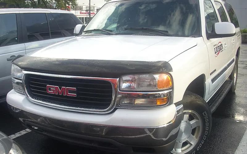
Common on this vehicle:Gauge or instrument faultWarning lightLeakNoiseCorrosion or rustMisfire or rough idleVibration or shudderAir conditioning or heater
Record by record
708 records state a cause or a remedy. Each record is shown as short labels in the order fault → finding the cause → correction. Press a label to narrow to the records that state it.
Symptom
Component named as the cause
Work done
How it is said to have ended
- says it held for a while1
- says it came back8
- says it did not fix it7
- result not stated21
A ribbon is as wide as the records that state both of its ends (only the commonest are drawn). A record that names several symptoms or components runs through each. Orange is records that say the fault came back or was not fixed. Results come from owners’ reports only; one that does not say is “result not stated”. None of this is a likelihood of a cause or a rate at which work succeeds.
Read the records one by one (33)
Known issuesHydro-boost brake assist and power steering share one hydraulic supply (four campaigns)3
Recall2004 GMC YUKON XL ・ 2005-08-02
Bosch Hydro-Boost Brake Accumulator Crack Recall
1Fault
- The hydraulic brake booster's pressure accumulator may crack and/or separate from the Hydro-Boost assembly in normal operation; if it separates with the hood open, fragments could injure people nearby.
- The crack or fractured surface could let hydraulic fluid leak from the accumulator circuit of the booster, and the loss of fluid would increase steering and braking effort.
2Finding the cause
Possible causes
- The over-pressurization comes from a two-function valve (TFV) that does not open within its specified limits while the hydraulic fluid in the accumulator circuit expands as the booster is exposed to rising under-hood temperatures.
Steps to confirm (in the document’s order)
- With the engine OFF, make at least five (5) high effort brake applies until the pedal feels hard.
- Turn the steering wheel to the steering lock (fully turned) position, hold for 1 to 2 seconds, then release; do this a total of 3 times.
- Install the inlet port adapter, CH 47950-2, into the booster supply port and slowly tighten it with a torque wrench to 16 N·m (12 lb ft).
- Install the accumulator pressure clamp, CH 47950-1, by sliding it over the accumulator so that it straddles the hydro-boost housing.
- If fluid comes out of the inlet port adapter at up to 65 N·m (48 lb ft) maximum torque on the clamp bolt, the hydro-boost booster assembly is OK.
3Correction
Repair
- If no fluid is seen, complete Steps 19-27 and repeat Steps 1-18; if no fluid is visible in the second evaluation, replace the hydro-boost unit.
- After the test, reinstall the supply hose/tube to the booster and tighten to 28 N·m (21 lb ft).
- When the booster is replaced, install the 4 booster to bulkhead nuts and tighten them to 36 N·m (26 lb ft).
Caution
- The inspection uses the Hydro-Boost Checking Tool, CH 47950, shipped to each dealer.
- After starting the engine, do not depress the brake pedal until instructed.
- Incorrect installation of the fixture washer will damage the accumulator end.
Read the sentences of the record
From the manufacturer’s document
- Applies to:The recall covers certain 2004 Chevrolet Kodiak and GMC TopKick; 2004-2005 Chevrolet Avalanche, Express, Silverado, Suburban; GMC Savana, Sierra, Yukon XL; and HUMMER H2 vehicles built within the listed VIN breakpoints.
- Applies to:GM limited the recall to dealer stock vehicles and sold vehicles with less than 150 days in service.
- Condition:The hydraulic brake booster's pressure accumulator may crack and/or separate from the Hydro-Boost assembly in normal operation; if it separates with the hood open, fragments could injure people nearby.
- Condition:The crack or fractured surface could let hydraulic fluid leak from the accumulator circuit of the booster, and the loss of fluid would increase steering and braking effort.
- Cause:The over-pressurization comes from a two-function valve (TFV) that does not open within its specified limits while the hydraulic fluid in the accumulator circuit expands as the booster is exposed to rising under-hood temperatures.
- Caution:The inspection uses the Hydro-Boost Checking Tool, CH 47950, shipped to each dealer.
- Confirm:With the engine OFF, make at least five (5) high effort brake applies until the pedal feels hard.
- Caution:After starting the engine, do not depress the brake pedal until instructed.
- Confirm:Turn the steering wheel to the steering lock (fully turned) position, hold for 1 to 2 seconds, then release; do this a total of 3 times.
- Confirm:Install the inlet port adapter, CH 47950-2, into the booster supply port and slowly tighten it with a torque wrench to 16 N·m (12 lb ft).
- Confirm:Install the accumulator pressure clamp, CH 47950-1, by sliding it over the accumulator so that it straddles the hydro-boost housing.
- Caution:Incorrect installation of the fixture washer will damage the accumulator end.
- Confirm:If fluid comes out of the inlet port adapter at up to 65 N·m (48 lb ft) maximum torque on the clamp bolt, the hydro-boost booster assembly is OK.
- Repair:If no fluid is seen, complete Steps 19-27 and repeat Steps 1-18; if no fluid is visible in the second evaluation, replace the hydro-boost unit.
- Repair:After the test, reinstall the supply hose/tube to the booster and tighten to 28 N·m (21 lb ft).
- Repair:When the booster is replaced, install the 4 booster to bulkhead nuts and tighten them to 36 N·m (26 lb ft).
- Cause
- CERTAIN TRUCKS, SPORT UTILITY VEHICLES, AND VANS EQUIPPED WITH BOSCH HYDRO-BOOST BRAKE ASSEMBLIES, THE HYDRAULIC BRAKE BOOSTER PRESSURE ACCUMULATOR MAY CRACK AND SEPARATE FROM THE HYDRO-BOOST ASSEMBLY DURING NORMAL OPERATING CONDITIONS.
- Remedy
- DEALERS WILL TEST THE HYDRO-BOOST ASSEMBLY FOR FUNCTIONAL OPERATION OF THE TWO-FUNCTION VALVE. IF THE HYDRO-BOOST ASSEMBLY FAILS THE TEST, DEALERS WILL REPLACE THE ASSEMBLY FREE OF CHARGE. THE RECALL BEGAN ON MARCH 23, 2005. OWNERS MAY CONTACT CHEVROLET AT 1-800-630-2438, GMC TRUCKS AT 1-866-996-9463 AND HUMMER AT 1-800-732-5493.
- Consequence
- IF A SEPARATION OCCURRED AND THE HOOD OF THE VEHICLE WERE OPEN, FRAGMENTS FROM THE ACCUMULATOR COULD CAUSE INJURY TO PEOPLE IN THE IMMEDIATE AREA. THE PRESENCE OF THIS CRACK OR FRACTURED SURFACE COULD ALLOW THE HYDRAULIC FLUID TO LEAK FROM THE ACCUMULATOR CIRCUIT OF THE BOOSTER ASSEMBLY. THE LOSS OF FLUID WOULD CAUSE INCREASED STEERING AND BRAKING EFFORT AND A CRASH MAY OCCUR WITHOUT PRIOR WARNING.
Recall2004 GMC YUKON XL ・ 2004-04-02
Brake Hydro-Boost Housing Relief Valve Bore Recall
1Fault
- The relief valve bore in the brake hydro-boost module may be out of specification, which could fracture the relief valve o-ring seal inside the module.
- If the seal fractures, the driver may hear during braking an engine compartment noise like the one made when the steering wheel is turned to a full stop, and may feel slightly higher steering effort while braking and parking.
- Under certain driving conditions a fractured seal may require slightly more brake pedal effort for the same deceleration, which could result in a crash without prior warning.
2Finding the cause
Possible causes
- Inspection found a machining error in the relief bore cavity of modules produced on one of the automated boring machines used for the base housing.
Steps to confirm (in the document’s order)
- Look at the color of the relief valve: if it is metallic yellow or looks like brass, no further action is required.
- If a yellow, pink or white paint mark is visible, no further inspection or repair is required, and any stamped number is to be disregarded.
- With no paint marks and a stamped number 2, 3 or 4 visible, no further inspection or repair is required.
- If a stamped number 1 is visible on the machined surface, the relief valve must be replaced.
3Correction
Repair
- With the ignition OFF, pump the brake pedal at least ten times.
- Unscrew the original relief valve from the hydraulic brake booster with the tool supplied with the new relief valve.
- Insert the new relief valve into the bore and tighten it to 17 N·m (13 lb ft).
- With the master cylinder mounted flush to the booster, install the nuts and tighten them to 33 N·m (24 lb ft).
Parts
- Part number 10398682, VALVE KIT, P/B BOOS CONT, quantity 1 per vehicle if required.
Part numbers printed in the document
The numbers are as the document prints them. The name and the replacing number are what the pages of GMPartsGiant, a reseller of genuine parts and not GM, state. Aftermarket equivalents are not checked here (the links only search by number). Confirm the fit for the vehicle (VIN) before ordering.
Caution
- Take care when working around the accumulator, which contains high-pressure compressed gas and hydraulic fluid.
- Do not blow compressed air into the bore or flush the valve bore with commercially available cleaners; this could damage the booster or master cylinder.
Read the sentences of the record
From the manufacturer’s document
- Applies to:The recall covers certain 2003 and 2004 model year Cadillac Escalade, Escalade EXT and Escalade ESV; Chevrolet Silverado, Avalanche, Suburban and Express; GMC Sierra, Yukon, Yukon XL and Savana; HUMMER H2; and 2004 model year Chevrolet Tahoe vehicles built within the listed VIN breakpoints.
- Condition:The relief valve bore in the brake hydro-boost module may be out of specification, which could fracture the relief valve o-ring seal inside the module.
- Condition:If the seal fractures, the driver may hear during braking an engine compartment noise like the one made when the steering wheel is turned to a full stop, and may feel slightly higher steering effort while braking and parking.
- Condition:Under certain driving conditions a fractured seal may require slightly more brake pedal effort for the same deceleration, which could result in a crash without prior warning.
- Cause:Inspection found a machining error in the relief bore cavity of modules produced on one of the automated boring machines used for the base housing.
- Confirm:Look at the color of the relief valve: if it is metallic yellow or looks like brass, no further action is required.
- Confirm:If a yellow, pink or white paint mark is visible, no further inspection or repair is required, and any stamped number is to be disregarded.
- Confirm:With no paint marks and a stamped number 2, 3 or 4 visible, no further inspection or repair is required.
- Confirm:If a stamped number 1 is visible on the machined surface, the relief valve must be replaced.
- Caution:Take care when working around the accumulator, which contains high-pressure compressed gas and hydraulic fluid.
- Repair:With the ignition OFF, pump the brake pedal at least ten times.
- Repair:Unscrew the original relief valve from the hydraulic brake booster with the tool supplied with the new relief valve.
- Caution:Do not blow compressed air into the bore or flush the valve bore with commercially available cleaners; this could damage the booster or master cylinder.
- Repair:Insert the new relief valve into the bore and tighten it to 17 N·m (13 lb ft).
- Repair:With the master cylinder mounted flush to the booster, install the nuts and tighten them to 33 N·m (24 lb ft).
- Parts:Part number 10398682, VALVE KIT, P/B BOOS CONT, quantity 1 per vehicle if required.
- Cause
- CERTAIN SPORT UTILITY VEHICLES, PICKUP TRUCKS, AND PASSENGER VANS FAIL TO COMPLY WITH THE REQUIREMENTS OF FEDERAL MOTOR VEHICLE SAFETY STANDARD NO. 135, ?PASSENGER CAR BRAKE SYSTEMS.? SOME OF THESE VEHICLES WERE PRODUCED WITH AN OUT-OF-SPECIFICATION BRAKE HYDRO-BOOST HOUSING RELIEF VALVE BORE.
- Remedy
- DEALERS ARE TO REPLACE THE HYDRO-BOOST RELIEF VALVE. THE RECALL BEGAN ON JUNE 18, 2004. OWNERS SHOULD CONTACT CADILLAC AT 1-866-982-2339; CHEVROLET AT 1-800-630-2438; GMC AT 1-866-996-9463; OR HUMMER AT 1-866-486-6376.
- Consequence
- CONSEQUENTLY, THE VALVE O-RING SEAL MAY FRACTURE. STEERING EFFORTS MAY BE SLIGHTLY INCREASED WHILE BRAKING OR PARKING. UNDER CERTAIN DRIVING CONDITIONS, A FRACTURED SEAL MAY REQUIRE A SLIGHT INCREASE IN THE APPLIED BRAKE PEDAL EFFORT TO ACHIEVE THE SAME VEHICLE DECELERATION RATE AS PRIOR TO THE SEAT FRACTURE.
Recall2004–2005 GMC YUKON XL ・ 2005-02-15
Hydraulic Brake Booster Pressure Accumulator Crack Recall
1Fault
2Finding the cause
3Correction
Not stated
What the documents say to do
Hydro-boost brake assist and power steering share one hydraulic supply (four campaigns)Confirm
- Perform the "Power Steering System Test" found in SI and make any necessary repairs based on system diagnosis.
Repair
- Dealers replace the hydro-boost relief valve.
- Dealers test the hydro-boost assembly for functional operation and replace it if it fails.
Caution
- An inoperative pump raises steering and braking effort but does not completely remove the ability to steer or slow the vehicle.
Read the sentences of the record
- Cause
- On certain vehicles, the hydraulic brake booster's pressure accumulator may crack and/or separate from the Hydro-Boost assembly during normal vehicle operating conditions. If a separation occurred and the hood of the vehicle was open, fragments from the accumulator could cause injury to people in the immediate area. In addition, the presence of this crack or fractured surface could allow the hydraulic fluid to leak from the accumulator circuit of the booster assembly. The loss of fluid would cause increased steering and braking effort. Correction: Dealers will test and, if necessary, replace the Hydro-Boost assembly.
Known issuesHVAC blower motor resistor module / connector overheating2
Recall2003–2006 GMC YUKON XL ・ 2011-02-21
HVAC Blower Motor Resistor Module Overheating
1Fault
2Finding the cause
3Correction
Not stated
What the documents say to do
HVAC blower motor resistor module / connector overheatingRepair
- Dealers install a new blower motor resistor and resistor module connector.
- Cut the wires back far enough to remove any melted insulation.
Caution
- The connector must be replaced even if it was replaced in an earlier repair.
Read the sentences of the record
- Cause
- On certain vehicles, the interface between the electrical terminals of the Heating, Ventilation, and Air Conditioning (HVAC) blower relay resistor module and the wiring connector (which powers the module) may be incapable of conducting higher current levels for sustained periods of operation. In addition, moisture and other contaminants (such as road de-icing materials) may enter the fresh air intake plenum and contact the internal circuit of the module or corrode the terminals. These conditions may cause the relay resistor module or wiring connector to overheat, causing various symptoms such as: the HVAC blower may not function on certain or all blower speed settings; a burning-plastic smell or smoke may be present in the vehicle, or; the HVAC blower may run continually with the ignition in the OFF position. These warning signs could, in certain instances, be leading indicators of an impending vehicle fire, which could result in property damage and/or personal injury. Correction: Owners will be provided with additional warranty coverage for the blower motor resistor module/wiring connector overheating condition. Under this "special warranty coverage", should this condition occur within 10 years or 240,000 km from first vehicle registration, dealers will install a replacement blower motor resistor and resistor module connector.
Owner complaint2004 GMC YUKON XL ・ 2011-08-11
Rear air conditioner malfunction
1Fault
2Finding the cause
3Correction
Read the sentences of the record
- Fault
- THE CONTACT STATED THAT THE AIR CONDITIONER IN THE REAR NO LONGER FUNCTIONED.
- Cause
- THE CONTACT FELT THAT THE FAILURE OF THE REAR AIR CONDITIONER WAS A MANUFACTURER'S DEFECT.
- Remedy
- THE DEALER REPLACED THE POWER CONNECTER AND THE RESISTER BLOWER.
Known issuesEngine fuel rail pulse damper retainer clip may fracture (8.1L V8) - recall 06V-289 / Transport Canada 20061952
Recall2004 GMC YUKON XL ・ 2006-03-08
Fuel Rail Pulse Damper Retainer Clip Fracture Recall
1Fault
- The engine fuel rail pulse damper retainer clip may fracture, resulting in inadequate retention of the damper; if the damper comes loose, a fuel leak may result and may cause a fire if an ignition source is present.
2Finding the cause
Possible causes
- Analysis showed some clips were not properly heat treated and were more susceptible to fracture.
Steps to confirm (in the document’s order)
- To inspect for leaks, turn the ignition ON with the engine OFF for 2 seconds, turn it OFF for 10 seconds, turn it ON with the engine OFF, and inspect the fuel rail, fuel rail dampener, and fuel rail pressure cap and valve for fuel leaks.
3Correction
Repair
- Dealers are to replace the engine fuel rail pulse damper retainer clip.
- Connect the J 34730-1A fuel pressure gage to the fuel pressure valve, wrapping a shop towel around the fitting while connecting it to avoid spillage.
- Open the valve on the J 34730-1A to bleed the system pressure; to help relieve residual pressure in the fuel rail, push down on the fuel rail dampener, which should move inward approximately 2-3 mm (1/8 in) as the pressure releases.
- Push down on the fuel dampener and remove the fuel pressure dampener clip; discard the old clip.
- Push down on the fuel dampener and install the new fuel pressure dampener clip.
Parts
- Part: 12575017 Clamp-Fuel Pulse Dpnr, quantity 1 per vehicle.
Part numbers printed in the document
The numbers are as the document prints them. The name and the replacing number are what the pages of GMPartsGiant, a reseller of genuine parts and not GM, state. Aftermarket equivalents are not checked here (the links only search by number). Confirm the fit for the vehicle (VIN) before ordering.
Caution
- The service procedure in this recall is different from the service procedure in the service manual.
- If the fuel pressure is not relieved as instructed in step 8, or the dampener is not held in position while the clip is replaced, the dampener O-ring may not seat or seal properly, and a damaged or improperly seated O-ring may result in a fuel leak.
- Do not remove the fuel dampener from the fuel rail; if it is removed, a fuel dampener kit with a new O-ring must be installed.
- The bulletin was revised to add new information to the service procedure: warning statements were added along with some other minor changes.
Read the sentences of the record
From the manufacturer’s document
- Applies to:Applies to certain 2004-06 Chevrolet Silverado, Suburban, Avalanche; GMC Sierra, Yukon XL; and 2006 Chevrolet Kodiak and GMC TopKick equipped with an 8.1L V8 (RPO L18 - VIN G) engine.
- Applies to:The defect notice lists GMC Yukon XL (GMT800): 2004 model year manufactured 03/2003 to 06/2004 (967 vehicles), 2005 manufactured 06/2004 to 06/2005 (658), and 2006 manufactured 07/2005 to 01/2006 (152).
- Condition:The engine fuel rail pulse damper retainer clip may fracture, resulting in inadequate retention of the damper; if the damper comes loose, a fuel leak may result and may cause a fire if an ignition source is present.
- Cause:Analysis showed some clips were not properly heat treated and were more susceptible to fracture.
- Repair:Dealers are to replace the engine fuel rail pulse damper retainer clip.
- Parts:Part: 12575017 Clamp-Fuel Pulse Dpnr, quantity 1 per vehicle.
- Caution:The service procedure in this recall is different from the service procedure in the service manual.
- Repair:Connect the J 34730-1A fuel pressure gage to the fuel pressure valve, wrapping a shop towel around the fitting while connecting it to avoid spillage.
- Repair:Open the valve on the J 34730-1A to bleed the system pressure; to help relieve residual pressure in the fuel rail, push down on the fuel rail dampener, which should move inward approximately 2-3 mm (1/8 in) as the pressure releases.
- Caution:If the fuel pressure is not relieved as instructed in step 8, or the dampener is not held in position while the clip is replaced, the dampener O-ring may not seat or seal properly, and a damaged or improperly seated O-ring may result in a fuel leak.
- Caution:Do not remove the fuel dampener from the fuel rail; if it is removed, a fuel dampener kit with a new O-ring must be installed.
- Repair:Push down on the fuel dampener and remove the fuel pressure dampener clip; discard the old clip.
- Repair:Push down on the fuel dampener and install the new fuel pressure dampener clip.
- Confirm:To inspect for leaks, turn the ignition ON with the engine OFF for 2 seconds, turn it OFF for 10 seconds, turn it ON with the engine OFF, and inspect the fuel rail, fuel rail dampener, and fuel rail pressure cap and valve for fuel leaks.
- Repair:If a leak is present, a dampener kit with a new O-ring must be installed.
- Caution:The bulletin was revised to add new information to the service procedure: warning statements were added along with some other minor changes.
- Cause
- ON CERTAIN TRUCKS EQUIPPED WITH AN 8.1L V8 (RPO L8-VIN G) ENGINE HAVE A CONDITION IN WHICH THE ENGINE FUEL RAIL PULSE DAMPER RETAINER CLIP MAY FRACTURE RESULTING IN INADEQUATE RETENTION OF THE DAMPER.
- Remedy
- DEALERS WILL REPLACE THE ENGINE FUEL RAIL PULSE DAMPER RETAINER CLIP FREE OF CHARGE. THE RECALL BEGAN ON AUGUST 31, 2006. OWNERS MAY CONTACT CHEVROLET AT 1-800-630-2438 AND GMC TRUCKS AT 1-866-996-9463.
- Consequence
- IF THE DAMPER COMES LOOSE, A FUEL LEAK MAY RESULT. FUEL LEAKAGE, IN THE PRESENCE OF AN IGNITION SOURCE, COULD RESULT IN A FIRE.
Recall2004–2006 GMC YUKON XL ・ 2006-08-04
Engine fuel rail pulse damper retainer clip fracture recall
1Fault
2Finding the cause
3Correction
Not stated
What the documents say to do
Engine fuel rail pulse damper retainer clip may fracture (8.1L V8) - recall 06V-289 / Transport Canada 2006195Confirm
- To inspect for leaks, turn the ignition ON with the engine OFF for 2 seconds, turn it OFF for 10 seconds, turn it ON with the engine OFF, and inspect the fuel rail, fuel rail dampener, and fuel rail pressure cap and valve for fuel leaks.
Repair
- Dealers replace the engine fuel rail pulse damper retainer clip.
- Dealers replace the engine fuel rail pulse damper retainer clip.
Caution
- The service procedure in this recall is different from the service procedure in the service manual.
Read the sentences of the record
- Cause
- On certain vehicles, the engine fuel rail pulse damper retainer clip may fracture, resulting in inadequate retention of the damper. If the damper comes loose, a fuel leak may result. Fuel leakage in the presence of an ignition source could result in a fire. Correction: Dealers will replace the engine fuel rail pulse damper retainer clip.
Known issuesInstrument panel cluster gauges stick, flutter or stop working2
Owner complaint2004 GMC YUKON XL ・ 2014-07-25
Speedometer and dashboard gauges intermittently malfunction
1Fault
2Finding the cause
Not stated
3Correction
TO REPAIR THEY HAVE TO REMOVE THE DASHBOARD. *TR
What the documents say to do
Instrument panel cluster gauges stick, flutter or stop workingRepair
- Dealers replace the instrument panel cluster after verifying the condition.
Read the sentences of the record
- Fault
- ALSO THE OTHER GAUGES IN DASH BOARD WILL QUIT WORKING. (2 more)
- Remedy
- TO REPAIR THEY HAVE TO REMOVE THE DASHBOARD. *TR
- Inspection
- I CHECKED WITH A MECHANIC AND HE SAYS THIS IS COMMON FOR THE MODEL I HAVE.
- Consequence
- IT HAS CAUSED BOTH MY HUSBAND TICKETS OR WARNINGS BECAUSE IT DOES NOT WORK.
Owner complaint2004 GMC YUKON XL ・ 2007-05-08
Speedometer reading incorrectly while driving
1Fault
2Finding the cause
3Correction
Read the sentences of the record
- Fault
- WHILST DRIVING ON I-10 IT WAS NOTED THE INDICATED SPEED WAS LESS THAN POSTED. (1 more)
- Remedy
- THE DEALER REPLACED THE INSTRUMENT CLUSTER .
- Consequence
- BY THE TIME I REALIZED THE SPEEDOMETER WAS READING INCORRECTLY I WAS ZOOMING PAST OTHER TRAFFIC.
Known issuesCastech cylinder head porosity crack (gradual coolant loss)1
Manufacturer communication2001–2006 GMC YUKON XL DENALI ・ 2024-03-19
Internal Coolant Leak from Cylinder Head Location
1Fault
- Some vehicles may experience a gradual coolant loss over time.
2Finding the cause
Possible causes
- A very low percentage of cylinder heads manufactured with an embossed Castech logo may develop a porosity crack in a very specific area.
Steps to confirm (in the document’s order)
- Check whether the head is a Castech casting by looking for the casting logo on top of the intake port, under the rocker arm support rail and in the spring deck cavity portion of the cylinder head.
- If the head is a Castech casting, inspect the area around the five oil drain holes for witness marks indicating coolant seepage over time.
- The crack can be in any of the five cylinder head oil drains and shows as a clean or shiny area on an otherwise stained surface.
- Pressurizing the cooling system at this time may reveal coolant, air, or a combination weeping in the described area.
3Correction
Repair
- If inspection reveals evidence of coolant witness marks, replace the entire cylinder head assembly.
Caution
- If the cylinder heads are not a Castech casting, follow normal diagnostic procedures in SI to determine the cause of the coolant loss.
- If no evidence of coolant loss is found on inspection of Castech casting cylinder heads, follow normal diagnostic procedures in SI to determine the cause of the coolant loss.
Read the sentences of the record
From the manufacturer’s document
- Applies to:Applies to 2001-2006 GMC Envoy, Jimmy, Sierra and Yukon models, among other listed GM models, with the 4.8L, 5.3L or 5.7L VORTEC GEN III, GEN IV V8 engine.
- Condition:Some vehicles may experience a gradual coolant loss over time.
- Cause:A very low percentage of cylinder heads manufactured with an embossed Castech logo may develop a porosity crack in a very specific area.
- Confirm:Check whether the head is a Castech casting by looking for the casting logo on top of the intake port, under the rocker arm support rail and in the spring deck cavity portion of the cylinder head.
- Confirm:If the head is a Castech casting, inspect the area around the five oil drain holes for witness marks indicating coolant seepage over time.
- Confirm:The crack can be in any of the five cylinder head oil drains and shows as a clean or shiny area on an otherwise stained surface.
- Confirm:Pressurizing the cooling system at this time may reveal coolant, air, or a combination weeping in the described area.
- Repair:If inspection reveals evidence of coolant witness marks, replace the entire cylinder head assembly.
- Caution:If the cylinder heads are not a Castech casting, follow normal diagnostic procedures in SI to determine the cause of the coolant loss.
- Caution:If no evidence of coolant loss is found on inspection of Castech casting cylinder heads, follow normal diagnostic procedures in SI to determine the cause of the coolant loss.
Open the manufacturer’s document (PDF) ↗ The points above were read from this document.
- Remedy
- This bulletin advises the technician of possible location of an internal coolant leak from a specific cylinder head and location.
Known issuesAftermarket part (not the vehicle as built): Federal-Mogul National / Carquest replacement wheel hub assembly retention nut - recall 07E-1061
Recall2004 GMC YUKON XL ・ —
Wheel Hub Assembly Bearing Nut Loosening Recall
1Fault
- The inboard retention nut that maintains the hub bearing assembly can loosen, resulting in an ABS light indication, noise, and/or wheel separation from the vehicle; wheel separation can result in a vehicle crash.
2Finding the cause
Steps to confirm (in the document’s order)
- On 2x4 vehicles, raise the vehicle on an approved hoist first; the hub assembly is good if a yellow, green or blue paint mark is seen on the grease cap on the inboard side of the steering knuckle.
- If the paint mark is not present, remove the wheel and the brake rotor and clean rust from the hub assembly face to check for the date code stamping.
- Defective hub assemblies can be identified by the country of origin on the package together with a recalled date code, by the date code on the package, or by the date code on the hub assembly.
- If a round yellow sticker is present on the box label, the part is good.
3Correction
Repair
- The hub assemblies were manufactured for aftermarket use; owners of these parts should have them removed and replaced as soon as possible.
- Federal-Mogul will replace the recalled hub assemblies free of charge.
Parts
- The recalled part numbers are 515020, 515021, 515025, 515053, 515054, 515059 and 515060.
Read the sentences of the record
From the manufacturer’s document
- Applies to:This is an equipment recall by Federal-Mogul of certain wheel hub assemblies sold as replacement parts only.
- Applies to:The recalled hub assemblies were packaged and sold between January 23, 2006 and December 20, 2007 under the National and CARQUEST Premium (BGS/Blue) brands, in 7 base part numbers.
- Parts:The recalled part numbers are 515020, 515021, 515025, 515053, 515054, 515059 and 515060.
- Applies to:The application lists include GMC 1500 Yukon (2WD) and GMC 1500 Yukon XL (2WD), 2001-2006.
- Applies to:ILJIN manufactured the recalled hub assemblies from December 27, 2005 to November 29, 2007.
- Condition:The inboard retention nut that maintains the hub bearing assembly can loosen, resulting in an ABS light indication, noise, and/or wheel separation from the vehicle; wheel separation can result in a vehicle crash.
- Confirm:On 2x4 vehicles, raise the vehicle on an approved hoist first; the hub assembly is good if a yellow, green or blue paint mark is seen on the grease cap on the inboard side of the steering knuckle.
- Confirm:If the paint mark is not present, remove the wheel and the brake rotor and clean rust from the hub assembly face to check for the date code stamping.
- Confirm:Defective hub assemblies can be identified by the country of origin on the package together with a recalled date code, by the date code on the package, or by the date code on the hub assembly.
- Confirm:If a round yellow sticker is present on the box label, the part is good.
- Repair:The hub assemblies were manufactured for aftermarket use; owners of these parts should have them removed and replaced as soon as possible.
- Repair:Federal-Mogul will replace the recalled hub assemblies free of charge.
- Cause
- CERTAIN FEDERAL-MOGUL REPLACEMENT WHEEL HUB ASSEMBLIES WITH THE BRAND NAMES: NATIONAL, CARQUEST P/NOS. 515020, 515021, 515025, 515053, 515054, 515059, AND 515060, SHIPPED BETWEEN JANUARY 23, 2006, AND DECEMBER 20, 2007, SOLD FOR LIGHT DUTY AND MEDIUM DUTY TRUCKS. THE INBOARD RETENTION NUT USED TO MAINTAIN HUB BEARING ASSEMBLY CAN LOOSEN RESULTING IN AN ABS LIGHT INDICATION, NOISE, AND/OR WHEEL SEPARATION.
- Remedy
- FEDERAL-MOGUL WILL NOTIFY CUSTOMERS AND WILL REPLACE THE HUB ASSEMBLY FREE OF CHARGE. THE RECALL BEGAN ON FEBRUARY 7, 2008. OWNERS CAN CONTACT FEDERAL-MOGUL TOLL-FREE AT 877-489-6659.
- Consequence
- WHEEL SEPARATION CAN RESULT IN A VEHICLE CRASH.
Known issuesHigher than expected oil consumption at 8600 GVW and above (accepted rate and consumption test)1
Manufacturer communication2001–2006 GMC YUKON XL DENALI ・ 2025-01-17(1 earlier editions of this document folded here)
Oil Consumption Measurement and Loss of Oil Service Bulletin
1Fault
Not stated
2Finding the cause
Possible causes
- Towing a trailer or hauling additional weight will increase oil consumption.
Steps to confirm (in the document’s order)
- The accepted rate of oil consumption for gasoline engines in vehicles at or above 8600 GVW is stated as 1 liter (1 qt) within 400 liters (100 gallons) of fuel used.
- Inspect the oil pans, engine covers and the engine oil cooler for leakage, and inspect for oil leakage into the engine coolant.
- Verify that the positive crankcase ventilation (PCV) system is operating properly; blockages, restrictions or damage to the PCV system can result in increased oil use.
- Wait at least 15 minutes after the engine is shut off before checking the oil level, so most of the oil has drained back into the crankcase.
- Check the oil level and record the vehicle mileage, date and exact oil level on the bulletin's form, then make sure the oil level is at, but not above, the full mark on the dipstick, adding oil if necessary.
3Correction
Repair
- If the final evaluation shows the engine uses more than 0.946 liter (1 qt) in 379 liters (100 gallons) of fuel used, follow the published symptom diagnostics in the appropriate Service Manual.
- The labor operation for the oil consumption test is 0600334, 0.5 hr.
Caution
- Part of the oil film left on the cylinder wall is consumed during combustion, so varying rates of oil consumption are accepted as normal in all engines.
- This rate applies only to vehicles under warranty, maintained per the appropriate maintenance schedule, driven at legal speeds and within the design intent of the vehicle.
- Oil economy should not be tested until the vehicle has accumulated at least 6400 km (4000 mi), except when an engine is reported to be using more than 0.946 liter (1 qt) in 1600 km (1000 mi).
Read the sentences of the record
From the manufacturer’s document
- Applies to:The model list includes the 2000–2019 Yukon XL, among other GM trucks and vans, with a gasoline engine and rated at 8600 GVW and above (note: the Yukon XL range runs to 2019).
- Caution:Part of the oil film left on the cylinder wall is consumed during combustion, so varying rates of oil consumption are accepted as normal in all engines.
- Confirm:The accepted rate of oil consumption for gasoline engines in vehicles at or above 8600 GVW is stated as 1 liter (1 qt) within 400 liters (100 gallons) of fuel used.
- Caution:This rate applies only to vehicles under warranty, maintained per the appropriate maintenance schedule, driven at legal speeds and within the design intent of the vehicle.
- Confirm:Inspect the oil pans, engine covers and the engine oil cooler for leakage, and inspect for oil leakage into the engine coolant.
- Confirm:Verify that the positive crankcase ventilation (PCV) system is operating properly; blockages, restrictions or damage to the PCV system can result in increased oil use.
- Cause:Towing a trailer or hauling additional weight will increase oil consumption.
- Caution:Oil economy should not be tested until the vehicle has accumulated at least 6400 km (4000 mi), except when an engine is reported to be using more than 0.946 liter (1 qt) in 1600 km (1000 mi).
- Confirm:Wait at least 15 minutes after the engine is shut off before checking the oil level, so most of the oil has drained back into the crankcase.
- Confirm:Check the oil level and record the vehicle mileage, date and exact oil level on the bulletin's form, then make sure the oil level is at, but not above, the full mark on the dipstick, adding oil if necessary.
- Confirm:Ask the customer to schedule an appointment and return to the dealer for inspection once they have consumed 100 gallons (= 378.5 L) of fuel.
- Repair:If the final evaluation shows the engine uses more than 0.946 liter (1 qt) in 379 liters (100 gallons) of fuel used, follow the published symptom diagnostics in the appropriate Service Manual.
- Repair:The labor operation for the oil consumption test is 0600334, 0.5 hr.
Open the manufacturer’s document (PDF) ↗ The points above were read from this document.
- Remedy
- This service bulletin explains how to measure for oil consumption and possible reasons for loss of oil.
Known issuesSome OnStar features no longer work (2G cellular sunset; the module is not broken)1
Manufacturer communication2003–2006 GMC YUKON XL DENALI ・ 2025-04-28
OnStar Module 2G Sunset Information
1Fault
- Customers may comment on a notification and/or that some 2G OnStar module features are no longer operable.
- One of the listed concerns is being unable to contact the OnStar Call Center.
- All other functions within the OnStar module are unaffected, such as OnStar remote link, Bluetooth, microphone, and GPS.
2Finding the cause
Possible causes
- On December 31, 2022, the 2G cellular signal will no longer be active, causing some OnStar module features to be inoperable.
- The 2G CDMA cellular network was decommissioned across Canada in 2015.
Steps to confirm (in the document’s order)
- Any other function in the Telematics Communication Interface Control Module (other than OnStar) is to be diagnosed as directed by SI.
3Correction
Repair
- The OnStar guardian app is being used as a replacement for the OnStar portion of the module.
Caution
- Do not replace the OnStar module because of the 2G shutdown.
- If the vehicle is brought in for inactive/broken/inoperable OnStar features, do not replace the module; the module is not broken.
Read the sentences of the record
From the manufacturer’s document
- Applies to:Applies to GMC Yukon models, model years 2003 to 2014.
- Applies to:The involved region is North America.
- Condition:Customers may comment on a notification and/or that some 2G OnStar module features are no longer operable.
- Condition:One of the listed concerns is being unable to contact the OnStar Call Center.
- Condition:All other functions within the OnStar module are unaffected, such as OnStar remote link, Bluetooth, microphone, and GPS.
- Cause:On December 31, 2022, the 2G cellular signal will no longer be active, causing some OnStar module features to be inoperable.
- Caution:Do not replace the OnStar module because of the 2G shutdown.
- Caution:If the vehicle is brought in for inactive/broken/inoperable OnStar features, do not replace the module; the module is not broken.
- Repair:The OnStar guardian app is being used as a replacement for the OnStar portion of the module.
- Confirm:Any other function in the Telematics Communication Interface Control Module (other than OnStar) is to be diagnosed as directed by SI.
- Cause:The 2G CDMA cellular network was decommissioned across Canada in 2015.
Open the manufacturer’s document (PDF) ↗ The points above were read from this document.
- Remedy
- This service bulletin provides information for dealers/technicians on OnStar Module 2G Sunset Information.
ELECTRICAL SYSTEM5
Owner complaint2004 GMC YUKON XL ・ 2014-03-31
Vehicle will not restart after short stops, takes 10 minutes to 4 hours
1Fault
2Finding the cause
3Correction
Not stated
Read the sentences of the record
- Fault
- WHEN I START THE VEHICLE AND GO TO THE CORNER STORE TURNING THE VEHICLE OFF, COME OUT OF STORE TO RESTART VEHICLE IT WILL NOT START IT MAY TAKE ME 10 MINUTES TO 4 HOURS TO GET THE VEHICLE STARTED AGAIN.
- Cause
- AT THIS TIME NOT SURE IF IT IS IGNITION SWITCH OR PASS LOCK I KNOW BOTH PARTS SHOULD BE COVERED BECAUSE IT IS A DEFAULT FROM THE MANUFACTURER. *TR
- Consequence
- MEANING I HAVE BEEN STRANDED AT GROCERY STORES, WORK, SCHOOL FUNCTIONS.
Manufacturer communication2000–2006 GMC YUKON XL DENALI ・ 2024-08-26
GM Vehicle Wide Programming (VWP) Software Update Process
1Fault
- Vehicle Wide Programming (VWP) is a new process to update software on GM vehicles.
2Finding the cause
Not stated
3Correction
Read the sentences of the record
From the manufacturer’s document
- Applies to:Various GM makes and models.
- Condition:Vehicle Wide Programming (VWP) is a new process to update software on GM vehicles.
Open the manufacturer’s document (PDF) ↗ The points above were read from this document.
- Remedy
- Vehicle Wide Programming (VWP) is a new process to update software on GM Vehicles. It provides the ability via a single selection within Techline Connect to first identify which modules need updating and then proceed to updating affected modules (with some exceptions). The updating of modules is completed in parallel instead of the technician needing to update one module at a time. This allows a more streamlined approach for dealers and customers.
Manufacturer communication2000–2006 GMC YUKON XL DENALI ・ 2024-06-25
Service Programming System Error Codes E4398-E6961 Service Information
1Fault
- Some technicians may notice Service Programming System (SPS) errors; the document gives the troubleshooting for them.
2Finding the cause
Not stated
3Correction
Read the sentences of the record
From the manufacturer’s document
- Applies to:Applies to GM passenger cars and light duty trucks, model years 2000 to 2025.
- Condition:Some technicians may notice Service Programming System (SPS) errors; the document gives the troubleshooting for them.
Open the manufacturer’s document (PDF) ↗ The points above were read from this document.
- Remedy
- This service bulletin provides information for dealers/technicians on Service Programming System (SPS) Error Codes E4398, E4399, E4401, E4403, M4404, M4413, M6954, M6955, E4414, E4423, E4491, E4492, or E6961 and resolution information.
Manufacturer communication2002–2006 GMC YUKON XL DENALI ・ 2024-04-05
Electrical Ground Repair Information
1Fault
Not stated
2Finding the cause
Possible causes
- Loose, stripped or corroded ground connections increase the possibility of improper system function and loss of module communication, and may lead to unnecessary repairs and component replacement.
3Correction
Repair
- For a damaged or missing M6 ground stud, select an adjacent location with 20 mm (0.79 in) clearance behind the panel surface and 20 mm (0.79 in) clearance around the M6 conductive rivet stud flange.
- Drill a 10 mm (0.40 in) diameter hole through the panel.
- Remove paint and primer from the area around the 10 mm (0.40 in) hole until bare metal is visible.
- Using a small brush, apply Dielectric Lubricant GM P/N 12377900 (Canadian P/N 10953529) to the threads of the M6 conductive rivet stud.
- Install the M6 conductive nut to the rivet stud and tighten to 71 lb in (= 8.02 N·m).
2 more pointsPart numbers printed in the document
12377900Lubricant, Dielectric Acdelco 2OzLook up at RockAuto (aftermarket candidates) ↗Search the web ↗
No successor statedas stated by GMPartsGiant (checked 2026-10-06) ↗
10953529Look up at RockAuto (aftermarket candidates) ↗Search the web ↗
The numbers are as the document prints them. The name and the replacing number are what the pages of GMPartsGiant, a reseller of genuine parts and not GM, state. Aftermarket equivalents are not checked here (the links only search by number). Confirm the fit for the vehicle (VIN) before ordering.
Parts
- Conductive-finish fasteners: 11561645 M6 nut, 11570340 M6 rivet stud, 11588564 M8 bolt, 11609412 M8 nut, 11609538 M7 bolt (self-threading), 11609669 M6 bolt.
Part numbers printed in the document
11561645NutLook up at RockAuto (aftermarket candidates) ↗Search the web ↗
No successor stated(replaces 11518173 / 11086223)as stated by GMPartsGiant (checked 2026-10-06) ↗
11570340Rivet, Stud W/Wedges Knurls And SealersLook up at RockAuto (aftermarket candidates) ↗Search the web ↗
No successor statedas stated by GMPartsGiant (checked 2026-10-06) ↗
11588564Bolt Assembly, Hx Head Fl Washer M, PointLook up at RockAuto (aftermarket candidates) ↗Search the web ↗
No successor statedas stated by GMPartsGiant (checked 2026-10-06) ↗
11609412Nut, Hexagon W/Conical Washer,M8X1.25, 7.5 Thick, 19 Outside DiameterLook up at RockAuto (aftermarket candidates) ↗Search the web ↗
No successor stated(replaces 11509226 / 22640336)as stated by GMPartsGiant (checked 2026-10-06) ↗
11609538Bolt/Screw, Tap Hexagon Head Trim Flat WasherLook up at RockAuto (aftermarket candidates) ↗Search the web ↗
No successor statedas stated by GMPartsGiant (checked 2026-10-06) ↗
11609669Bolt/Screw, Hx Head Flt WasherLook up at RockAuto (aftermarket candidates) ↗Search the web ↗
No successor stated(replaces 11517342 / 10156138)as stated by GMPartsGiant (checked 2026-10-06) ↗
The numbers are as the document prints them. The name and the replacing number are what the pages of GMPartsGiant, a reseller of genuine parts and not GM, state. Aftermarket equivalents are not checked here (the links only search by number). Confirm the fit for the vehicle (VIN) before ordering.
Caution
- Use only the GM-approved replacement fasteners with conductive finish for electrical ground repair.
- The rivet stud and surrounding panel area must be refinished before the ground wire terminal and conductive nut are installed, to keep the ground secure, stable and corrosion-free.
Read the sentences of the record
From the manufacturer’s document
- Applies to:Applies to 2024 and earlier GM passenger cars and trucks, including medium duty and heavy duty.
- Cause:Loose, stripped or corroded ground connections increase the possibility of improper system function and loss of module communication, and may lead to unnecessary repairs and component replacement.
- Caution:Use only the GM-approved replacement fasteners with conductive finish for electrical ground repair.
- Repair:For a damaged or missing M6 ground stud, select an adjacent location with 20 mm (0.79 in) clearance behind the panel surface and 20 mm (0.79 in) clearance around the M6 conductive rivet stud flange.
- Repair:Drill a 10 mm (0.40 in) diameter hole through the panel.
- Repair:Remove paint and primer from the area around the 10 mm (0.40 in) hole until bare metal is visible.
- Caution:The rivet stud and surrounding panel area must be refinished before the ground wire terminal and conductive nut are installed, to keep the ground secure, stable and corrosion-free.
- Repair:Using a small brush, apply Dielectric Lubricant GM P/N 12377900 (Canadian P/N 10953529) to the threads of the M6 conductive rivet stud.
- Repair:Install the M6 conductive nut to the rivet stud and tighten to 71 lb in (= 8.02 N·m).
- Repair:If the M6 weld nut at the ground location is damaged or stripped, a M7 conductive self-threading bolt may be used to secure the ground wire terminal.
- Repair:Install the M7 conductive self-threading bolt and tighten to 80 lb in (= 9.04 N·m).
- Parts:Conductive-finish fasteners: 11561645 M6 nut, 11570340 M6 rivet stud, 11588564 M8 bolt, 11609412 M8 nut, 11609538 M7 bolt (self-threading), 11609669 M6 bolt.
Open the manufacturer’s document (PDF) ↗ The points above were read from this document.
- Remedy
- This bulletin provides information for electrical ground repairs using new General Motors replacement fasteners with conductive finish.
Manufacturer communication2003–2006 GMC YUKON XL DENALI ・ 2023-12-26
Speedometer Needle Accuracy Information
1Fault
- A customer may say the speedometer needle appears inaccurate.
2Finding the cause
Possible causes
- The speedometer needle is driven electrically by a stepper motor and some variation in accuracy is possible.
- Tire size, tread life and inflation may cause some variation in the readings.
Steps to confirm (in the document’s order)
- Digital readouts such as the "Digital Speedometer" on the DIC read the Vehicle Speed Sensor (VSS) directly and are much more accurate.
- The specification for needle accuracy is +/- 2 MPH (= 3.22 km/h) at any given speed when looking straight at the needle.
3Correction
Read the sentences of the record
From the manufacturer’s document
- Applies to:Applies to 2003-2015 GMC Sierra and Yukon models (note: the Yukon years run later than the years this service covers).
- Condition:A customer may say the speedometer needle appears inaccurate.
- Cause:The speedometer needle is driven electrically by a stepper motor and some variation in accuracy is possible.
- Confirm:Digital readouts such as the "Digital Speedometer" on the DIC read the Vehicle Speed Sensor (VSS) directly and are much more accurate.
- Cause:Tire size, tread life and inflation may cause some variation in the readings.
- Confirm:The specification for needle accuracy is +/- 2 MPH (= 3.22 km/h) at any given speed when looking straight at the needle.
Open the manufacturer’s document (PDF) ↗ The points above were read from this document.
- Remedy
- Speedometer Needle Accuracy Information.
UNKNOWN OR OTHER4
Manufacturer communication2001–2006 GMC YUKON XL DENALI ・ 2025-07-23
TAC diagnostic assistance pico file requirement
1Fault
- Vehicle vibration under any of various driving conditions.
2Finding the cause
Possible causes
- Vibration could be caused by many various components and conditions.
Steps to confirm (in the document’s order)
- Drive the vehicle to verify the condition and record a Pico data file of the concern.
3Correction
Repair
- Repair the vehicle using the Pico information along with any published information relevant to the vibration frequency observed.
Caution
- Just as a check engine light is not repaired without knowing the stored DTC, a vibration should not be repaired without knowing its frequency.
- Bulletin 12-03-10-001B is a generic document about tire to rim orientation and the tire slipping on the rim.
- Component level vibrations such as a blower motor, brake pulsation or shudder on turns do not require a Pico file.
Read the sentences of the record
From the manufacturer’s document
- Applies to:Applies to all 2000 to 2026 models.
- Condition:Vehicle vibration under any of various driving conditions.
- Cause:Vibration could be caused by many various components and conditions.
- Caution:Just as a check engine light is not repaired without knowing the stored DTC, a vibration should not be repaired without knowing its frequency.
- Confirm:Drive the vehicle to verify the condition and record a Pico data file of the concern.
- Repair:Repair the vehicle using the Pico information along with any published information relevant to the vibration frequency observed.
- Caution:Bulletin 12-03-10-001B is a generic document about tire to rim orientation and the tire slipping on the rim.
- Caution:Component level vibrations such as a blower motor, brake pulsation or shudder on turns do not require a Pico file.
Open the manufacturer’s document (PDF) ↗ The points above were read from this document.
- Remedy
- This PI communicates the requirement to provide a pico file to receive diagnostic assistance from TAC.
Manufacturer communication2003–2006 GMC YUKON XL DENALI ・ 2024-09-06
Tire and Wheel Size Change Information
1Fault
- A request may be made to change the tire size on a vehicle.
2Finding the cause
Steps to confirm (in the document’s order)
- A calibration exists if, using the sales order guide, a vehicle of the same make, model year and trim can be built with that tire within the restrictions in the tire section.
3Correction
Caution
- GM supports a tire calibration only for tires that have been sized, tested and designed for the vehicle in question and its applications.
- There may be a cost to the customer for this service; it is not covered under the manufacturer's warranty.
Read the sentences of the record
From the manufacturer’s document
- Applies to:The model table lists all brands and models for model years 2003 - 2025, with exceptions marked.
- Applies to:Silverado Med Duty and LCF models are excepted.
- Condition:A request may be made to change the tire size on a vehicle.
- Caution:GM supports a tire calibration only for tires that have been sized, tested and designed for the vehicle in question and its applications.
- Confirm:A calibration exists if, using the sales order guide, a vehicle of the same make, model year and trim can be built with that tire within the restrictions in the tire section.
- Caution:There may be a cost to the customer for this service; it is not covered under the manufacturer's warranty.
Open the manufacturer’s document (PDF) ↗ The points above were read from this document.
- Remedy
- This Preliminary Information communication provides information to the technician about changing the tire and wheel size on vehicles. General Motors will only support a tire calibration for tires that have been sized, tested and designed for the vehicle in question and its applications. Technician should not use the information that is provided by the antilock braking system tire size selection.
Manufacturer communication2000–2006 GMC YUKON XL DENALI ・ 2024-07-12(1 earlier editions of this document folded here)
Product Assistance Claim (PAC) Information Bulletin
1Fault
- The bulletin describes how to work with GM on a Product Assistance Claim (PAC); it is for the U.S. only.
2Finding the cause
Not stated
3Correction
Read the sentences of the record
From the manufacturer’s document
- Applies to:Applies to 2025 and prior passenger cars and light/medium duty trucks.
- Condition:The bulletin describes how to work with GM on a Product Assistance Claim (PAC); it is for the U.S. only.
Open the manufacturer’s document (PDF) ↗ The points above were read from this document.
- Remedy
- This bulletin provides information for use on a Product Assistance Claim (PAC), which is formerly known as a Product Allegation Resolution (PAR) claim.
Manufacturer communication2003–2006 GMC YUKON XL DENALI ・ 2024-05-31
Warranty Administration Bulletin – Personal Property Damage Process
1Fault
- The bulletin gives the policies and warranty transaction procedures for the Personal Property Damage process.
2Finding the cause
Not stated
3Correction
Read the sentences of the record
From the manufacturer’s document
- Applies to:Applies to 2025 and prior GM passenger cars and light duty trucks.
- Condition:The bulletin gives the policies and warranty transaction procedures for the Personal Property Damage process.
Open the manufacturer’s document (PDF) ↗ The points above were read from this document.
- Remedy
- This Warranty Administration bulletin provides retail and wholesale service personnel with the policies/procedures and the warranty transaction submission procedures that support the Personal Property Damage process.
ENGINE2
Owner complaint2004 GMC YUKON DENALI XL ・ 2015-09-23
Engine stalls while driving at approximately 60 MPH
1Fault
2Finding the cause
Not stated
3Correction
Read the sentences of the record
- Fault
- WHILE DRIVING APPROXIMATELY 60 MPH (= 96.6 km/h), THE VEHICLE STALLED. (1 more)
- Remedy
- THE MECHANIC REPLACED THE TAC MODULE AND ELECTRONIC THROTTLE BODY, BUT THE FAILURE RECURRED. (1 more)
Manufacturer communication2000–2006 GMC YUKON XL DENALI ・ 2024-07-16(1 earlier editions of this document folded here)
Fuel Injection Cleaner Kit Service Bulletin
1Fault
- Hard start or long crank
- Misfire or rough idle
- Does not start
- Warning light
- Check engine / Service Engine Soon
- P0300
- P0301
- P0302
- P0303
- P0304
- P0305
- Rough idle, crank no start, extended crank or misfire, with the engine warning lamp on and DTC P0300, P0301, P0302, P0303, P0304, P0305, P0306, P0307 or P0308 set.
- When the engine is cold, compression on multiple cylinders may be zero.
- The engine may pop through the intake or exhaust while cranking, and the spark plugs may be fuel fouled.
2Finding the cause
Possible causes
- Major carbon build-up on the intake and/or exhaust valves from fuel contamination or incomplete burning of the fuel; misfires should not appear before at least 8,000 km (5,000 mi).
3Correction
Repair
- If there is no valve damage and no cam follower out of place, perform the cleaning procedure to free sticking valves and remove carbon from the valves and pistons.
- If valves are damaged or cam followers are out of place, make the engine mechanical repairs first and then perform the cleaning procedure to prevent a return.
- Fill Cleaner Kit J-35800-A with about 650 ml (22 oz, 2 cans) of Air Intake, Combustion Chamber Cleaner and set the air pressure at the tool to 260 kPa (40 psi).
- With GDS 2 or a scan tool, command engine idle to 2000 rpm so the engine does not stall.
- With the engine at operating temperature in a well-ventilated area, slowly and carefully induce the cleaner into the engine, taking about 3 minutes.
Parts
- The Top Engine Cleaning Kit (ACDelco Air Intake, Valve and Combustion Chamber Cleaner and ACDelco Fuel System Cleaner 44K) is 19435372 for the U.S. and Canada.
Part numbers printed in the document
19435372MAINTENANCE KIT,FUEL SYSTEM ACDELCO 3-11OZLook up at RockAuto (aftermarket candidates) ↗Search the web ↗
No successor statedas stated by GMPartsGiant (checked 2026-10-06) ↗
The numbers are as the document prints them. The name and the replacing number are what the pages of GMPartsGiant, a reseller of genuine parts and not GM, state. Aftermarket equivalents are not checked here (the links only search by number). Confirm the fit for the vehicle (VIN) before ordering.
Caution
- Inducing too much cleaner at too low an RPM, or stalling the engine with too much cleaner at once, may hydro-lock the engine and bend a connecting rod.
Read the sentences of the record
From the manufacturer’s document
- Applies to:Applies to GM passenger cars and trucks with gasoline engines only, model years 2000 to 2025.
- Condition:Rough idle, crank no start, extended crank or misfire, with the engine warning lamp on and DTC P0300, P0301, P0302, P0303, P0304, P0305, P0306, P0307 or P0308 set.
- Condition:When the engine is cold, compression on multiple cylinders may be zero.
- Condition:The engine may pop through the intake or exhaust while cranking, and the spark plugs may be fuel fouled.
- Cause:Major carbon build-up on the intake and/or exhaust valves from fuel contamination or incomplete burning of the fuel; misfires should not appear before at least 8,000 km (5,000 mi).
- Repair:If there is no valve damage and no cam follower out of place, perform the cleaning procedure to free sticking valves and remove carbon from the valves and pistons.
- Repair:If valves are damaged or cam followers are out of place, make the engine mechanical repairs first and then perform the cleaning procedure to prevent a return.
- Caution:Inducing too much cleaner at too low an RPM, or stalling the engine with too much cleaner at once, may hydro-lock the engine and bend a connecting rod.
- Repair:Fill Cleaner Kit J-35800-A with about 650 ml (22 oz, 2 cans) of Air Intake, Combustion Chamber Cleaner and set the air pressure at the tool to 260 kPa (40 psi).
- Repair:With GDS 2 or a scan tool, command engine idle to 2000 rpm so the engine does not stall.
- Repair:With the engine at operating temperature in a well-ventilated area, slowly and carefully induce the cleaner into the engine, taking about 3 minutes.
- Parts:The Top Engine Cleaning Kit (ACDelco Air Intake, Valve and Combustion Chamber Cleaner and ACDelco Fuel System Cleaner 44K) is 19435372 for the U.S. and Canada.
Open the manufacturer’s document (PDF) ↗ The points above were read from this document.
- Remedy
- This service bulletin advises of a new fuel injection cleaner kit used for decarbonizing the intake valves to correct conditions of rough idle, Crank no start, extended crank or misfire, MIL with DTCs, and explains how Top Tier fuels should be used to reduce carbon build-up.
ENGINE AND ENGINE COOLING2
Manufacturer communication2000–2006 GMC YUKON XL DENALI ・ 2024-02-29
Oil Cooler, Oil Cooler Lines, and Oil Tank Replacement Service Information
1Fault
Not stated
2Finding the cause
Possible causes
- Debris from a damaged rod or main bearing is sent directly through the oil galleries and the components in the lubrication circuit.
3Correction
Repair
- Whenever an engine assembly is replaced for a connecting rod or crankshaft main bearing failure, also replace the oil cooler, oil cooler lines, oil tank and turbocharger, if equipped.
- If the oil cooler is part of the radiator assembly, the radiator must be replaced along with the other required components.
Caution
- Reinstalling an oil cooler or cooler line from an engine with bearing failure debris may carry remaining debris into the new service engine.
- Some service engines come with the oil cooler and/or oil cooler lines already attached; those need not be replaced.
- Not every engine with bearing damage requires the oil cooler, lines or oil tank, or even the engine, to be replaced.
Read the sentences of the record
From the manufacturer’s document
- Applies to:Applies to all GM passenger cars and trucks, 2000 through 2024, gasoline engines only.
- Repair:Whenever an engine assembly is replaced for a connecting rod or crankshaft main bearing failure, also replace the oil cooler, oil cooler lines, oil tank and turbocharger, if equipped.
- Repair:If the oil cooler is part of the radiator assembly, the radiator must be replaced along with the other required components.
- Cause:Debris from a damaged rod or main bearing is sent directly through the oil galleries and the components in the lubrication circuit.
- Caution:Reinstalling an oil cooler or cooler line from an engine with bearing failure debris may carry remaining debris into the new service engine.
- Caution:Some service engines come with the oil cooler and/or oil cooler lines already attached; those need not be replaced.
- Caution:Not every engine with bearing damage requires the oil cooler, lines or oil tank, or even the engine, to be replaced.
Open the manufacturer’s document (PDF) ↗ The points above were read from this document.
- Remedy
- This service bulletin provides service information to technicians on guidelines to replace Oil Cooler, Oil Cooler Lines and Oil Tank if the engine was replaced where large amounts of debris has flowed throughout the oiling system.
Manufacturer communication2000–2006 GMC YUKON XL DENALI ・ 2024-02-02
1Fault
Not stated
2Finding the cause
Steps to confirm (in the document’s order)
- Refer to the Engine Mechanical Specification in SI for the correct bore and piston specification.
3Correction
Repair
- When installing a piston into a cylinder, use a ring compressor sleeve or equivalent for best results.
- Choose a sleeve with a smooth radius that tapers down to the specific bore size.
- Select a size only slightly bigger than the piston diameter and not larger than the cylinder bore diameter.
Caution
- If a sleeve is unavailable in the needed size, a universal ring compressor will work but is more difficult to use.
Read the sentences of the record
From the manufacturer’s document
- Applies to:Applies to 2024 and earlier GM passenger cars and trucks.
- Repair:When installing a piston into a cylinder, use a ring compressor sleeve or equivalent for best results.
- Repair:Choose a sleeve with a smooth radius that tapers down to the specific bore size.
- Repair:Select a size only slightly bigger than the piston diameter and not larger than the cylinder bore diameter.
- Confirm:Refer to the Engine Mechanical Specification in SI for the correct bore and piston specification.
- Caution:If a sleeve is unavailable in the needed size, a universal ring compressor will work but is more difficult to use.
Open the manufacturer’s document (PDF) ↗ The points above were read from this document.
- Remedy
- This PI bulletin advises the technician on the proper way to install the pistons in an engine.
EQUIPMENT2
Manufacturer communication2002–2006 GMC YUKON XL DENALI ・ 2024-04-01
XM Audio Traffic and Travel Link Availability and Operation
1Fault
- A customer may have questions about which XM offerings are available for their vehicle.
2Finding the cause
Not stated
3Correction
XM Audio Traffic And Travel Link Availability And Operation.
Read the sentences of the record
From the manufacturer’s document
- Applies to:Applies to 2002-2015 GM passenger cars and light-duty trucks with XM radio.
- Condition:A customer may have questions about which XM offerings are available for their vehicle.
Open the manufacturer’s document (PDF) ↗ The points above were read from this document.
- Remedy
- XM Audio Traffic And Travel Link Availability And Operation.
Manufacturer communication2000–2006 GMC YUKON XL DENALI ・ 2024-01-08
1Fault
- Until the ignition recall repairs are done, customers should remove all items from the key ring, leaving only the vehicle key, and always use their seat belts.
2Finding the cause
Not stated
3Correction
Read the sentences of the record
From the manufacturer’s document
- Applies to:GM announced six new safety recalls in the United States involving about 7.6 million vehicles from the 1997 to 2014 model years.
- Condition:Until the ignition recall repairs are done, customers should remove all items from the key ring, leaving only the vehicle key, and always use their seat belts.
Open the manufacturer’s document (PDF) ↗ The points above were read from this document.
- Remedy
- Vehicle Recalls
BRAKES1
Recall2003–2004 GMC YUKON XL ・ 2004-01-29
Brake hydro-boost module relief valve o-ring seal failure
1Fault
2Finding the cause
3Correction
Not stated
Read the sentences of the record
- Cause
- On certain vehicles, the relief valve o-ring seal within the brake hydro-boost module could fail. If this happens during braking applications, the driver may be able to hear an engine compartment noise similar to the sound that occurs when the steering wheel is turned to a full stop position. The driver could also experience a slight increase in steering efforts while braking and parking. Under certain driving conditions, a slight increase in the applied brake pedal effort may be required to achieve the same vehicle deceleration rate as prior to the seal failure. Correction: Dealers will inspect the hydro-boost module, and replace it, if necessary.
EXTERIOR LIGHTING1
Manufacturer communication2001–2006 GMC YUKON XL DENALI ・ 2024-01-19
Headlamp, Tail Lamp, License Lamp or Fog/Driving Lamp Damage
1Fault
2Finding the cause
Possible causes
- A variety of chemicals can cause crazing or cracking of the polycarbonate lens.
- Bulbs with a higher output than original equipment run hotter, and the excess heat can melt the socket, housing or lens.
Steps to confirm (in the document’s order)
- Broken mounting tabs, rear housing fractures and loose components inside the lamp assembly are evidence of impact damage.
3Correction
Repair
- When servicing any exterior lighting assembly, transfer any electrical connection seals to the new part.
Caution
- Clean exterior lamps and lenses only with lukewarm or cold water, a soft cloth and a car washing soap.
- Do not let a shop mat or fender cover drape over a headlamp while the DRL or headlamps are on; the lens may craze or deform.
Read the sentences of the record
From the manufacturer’s document
- Applies to:Applies to 2024 and prior GM passenger cars and trucks.
- Cause:A variety of chemicals can cause crazing or cracking of the polycarbonate lens.
- Caution:Clean exterior lamps and lenses only with lukewarm or cold water, a soft cloth and a car washing soap.
- Caution:Do not let a shop mat or fender cover drape over a headlamp while the DRL or headlamps are on; the lens may craze or deform.
- Confirm:Broken mounting tabs, rear housing fractures and loose components inside the lamp assembly are evidence of impact damage.
- Cause:Bulbs with a higher output than original equipment run hotter, and the excess heat can melt the socket, housing or lens.
- Repair:When servicing any exterior lighting assembly, transfer any electrical connection seals to the new part.
Open the manufacturer’s document (PDF) ↗ The points above were read from this document.
- Remedy
- This informational bulletin provides information for dealers/technicians on Headlamp, Tail Lamp, License Lamp or Fog/Driving Lamp Damage.
POWER TRAIN1
Manufacturer communication2000–2006 GMC YUKON XL DENALI ・ 2024-08-15
Transmission Core Damage Prevention Notice
1Fault
- GM is receiving many cracked or broken transmission cores at the remanufacturing facilities, and the damage makes them unusable for remanufacturing.
2Finding the cause
3Correction
Read the sentences of the record
From the manufacturer’s document
- Applies to:Applies to 2000 to 2024 GM passenger cars, SUVs and light/medium duty trucks.
- Condition:GM is receiving many cracked or broken transmission cores at the remanufacturing facilities, and the damage makes them unusable for remanufacturing.
Open the manufacturer’s document (PDF) ↗ The points above were read from this document.
- Remedy
- GM is receiving damaged (cracked or broken) transmission cores returned to the reman facilities. The damage is being caused either in the removal process by the technician, or inadequate packaging or shipping. This bulletin advises the dealers to be more careful not to damage the transmissions during removal and to package the core properly for return.
SEATS AND RESTRAINTS1
Recall2003–2005 GMC YUKON XL ・ 2005-04-25
2nd Row Centre Seat Belt Routing Recall
1Fault
2Finding the cause
3Correction
Not stated
Read the sentences of the record
- Cause
- On certain vehicles, the 2nd row centre occupant seat belt routing may make it difficult to position the lap portion of the safety belt low around the hips of occupants. A lap portion of the seat belt routing that is not low and snug on the hips can allow unfavourable occupant kinetics in the event of a crash. Moreover, the higher routing allows the lap belt to ride up on an occupant's abdomen instead of fitting low around their hipbones, and therefore, can expose them to more risk of abdominal and internal organ injury. Correction: Dealers will modify the guide loop.
SERVICE BRAKES1
Owner complaint2004 GMC YUKON XL ・ 2022-04-27
Sudden speed reduction and high RPMs while driving; later brake engagement and smoke from wheel
1Fault
2Finding the cause
3Correction
Read the sentences of the record
- Fault
- While driving on the freeway at 75 mph (= 120.7 km/h) I felt significant reduction in speed and the rpms went pretty high. (5 more)
- Cause
- Possibly the proportioning valve.
- Remedy
- I replaced those anyway.
- Inspection
- This continued to happen sporadically so I took it to my mechanic he inspected the vehicle could not find an issue he also ran a code scan. (3 more)
Showing 33 of the 708 you can open. Narrow the search to see the rest.
16 owner complaints have no classified sentences yet, so their causes and repairs are not picked out. Their text is in the list of records.