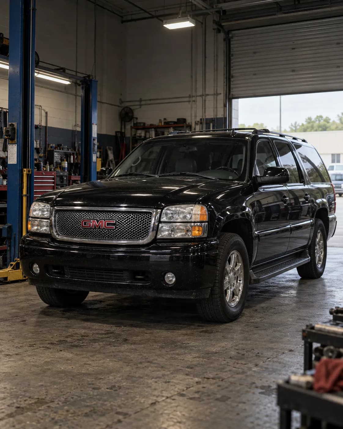
Source reference 10113770
Manufacturer communication — 2006 GMC YUKON DENALI XL
Relation to the target vehicle
- The source's vehicle field includes the trim.
- Model year
- Match 2006 — Source vehicle field
- Model
- Match YUKON DENALI XL — Source vehicle field
- Trim
- Match Denali — Source vehicle field
What the manufacturer’s document says
00-05-22-002O ・ information ・ for GM vehicles in general
Applies to
Applies to 2014 and prior GM passenger cars and light duty trucks.
the passage
2014 and Prior GM Passenger Cars and Light Duty Trucks
Finding the cause
Steps to confirm (in the document’s order)
Bench lathe: after refinishing a rotor, loosen the arbor nut and, holding the inside bell clamp so it does not rotate, rotate the rotor 180 degrees.
the passage
After refinishing a rotor, loosen the arbor nut and while holding the inside bell clamp to keep it from rotating, rotate the rotor 180 degrees.
Retighten the arbor nut, set the dial indicator on the rotor as when checking runout on the vehicle, then rotate the arbor and read the runout.
the passage
Retighten the arbor nut and set the dial indicator on the rotor using the same instructions as checking the run out on the vehicle. 3. Rotate the arbor and read the runout.
Divide the reading by two; that is the amount of runout the lathe is cutting into the rotor.
the passage
Divide the reading by two and this will give you the amount of runout the lathe is cutting into the rotor.
On-car lathe: attach a vise-grip dial indicator to a fixed point in the wheel well and bring the indicator to a flat surface on the cutting head.
the passage
Attach a vise-grip dial indicator to a fixed point in the wheel well and bring the dial indicator to a flat surface on the cutting head.
After compensation, if runout exceeds 0.1016 mm (0.004 in), or 0.050 mm (0.002 in) as measured within the rotor diameter, the lathe calibration must be checked.
the passage
If runout is in excess of 0.1016 mm (0.004 in) (0.050 mm (0.002 in) as measured within the rotor diameter), calibration must be checked.
Correction
Repair
If there is any runout, machine the inside bell clamp in place on the lathe; this is for a bench type lathe only and must not be done on an on-car lathe.
the passage
If there is any runout, you will need to machine the inside bell clamp in place on the lathe (this procedure is for a Bench type lathe ONLY, DO NOT machine inside the bell clamp on an On-Car type lathe).
Remove any nicks or burrs on the shoulder of the arbor; an 80-grit stone can be used.
the passage
Any nicks or burrs on the shoulder of the arbor must be removed. An 80-grit stone can be used to accomplish this.
Caution
Calibrate the brake lathe and record it monthly, or whenever lateral runout (LRO) measured on rotors after service is consistently above specification.
the passage
Calibration of the brake lathe should be performed and recorded monthly or whenever post-service brake rotor LRO measurements are consistently reading above specification.
Cuts of 0.1016-0.381 mm (0.004-0.015 in) give the best surface finish and the optimal tip life.
the passage
Cuts of 0.1016-0.381 mm (0.004-0.015 in) will provide the best surface finish and the optimal tip life.
The tool holder plate can bend or break if the cutting arms run into the hub of the turning rotor; cuts of more than 0.508 mm (0.020 in) can also bend it.
the passage
It can bend or break if a technician accidently runs the cutting arms into the hub of the rotor while the rotor is turning. (Cuts of more than 0.508 mm (0.020 in) can also bend this plate).
Compiled by reading the full text of the document; each point stands on the passage shown. Check the document itself, linked below, before working on a vehicle.
Stated content
Communication summary
本技術情報提供資料は、ブレーキレース研磨機の校正手順について技術者に提供するものです。 Machine translation (unreviewed)
This informational bulletin provides technicians with a brake lathe calibration procedure.
Go to this passage in the original
Source
- Source
- NHTSA Manufacturer Communications
- Source reference
- 10113770
- Received by source
- 2017-08-15
- Incident date
- Unknown
Open original text and sourceOpen the provider's page (external)