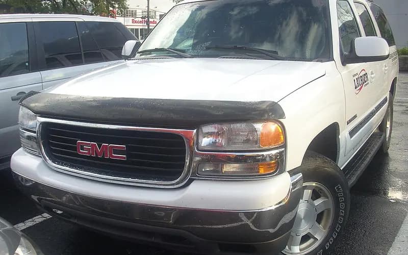
GMC Yukon XL 2000–2006
Common on this vehicle:Warning lightLeakGauge or instrument faultNoiseCorrosion or rustVibration or shudderAir conditioning or heaterSmoke or fire
Record by record
82 records state a cause or a remedy. Each record is shown as short labels in the order fault → finding the cause → correction. Press a label to narrow to the records that state it.
Component named as the cause
Work done
How it is said to have ended
- says it did not fix it4
- result not stated1
A ribbon is as wide as the records that state both of its ends (only the commonest are drawn). A record that names several symptoms or components runs through each. Orange is records that say the fault came back or was not fixed. Results come from owners’ reports only; one that does not say is “result not stated”. None of this is a likelihood of a cause or a rate at which work succeeds.
Read the records one by one (15)
Known issuesAftermarket part (not the vehicle as built): Federal-Mogul National / Carquest replacement wheel hub assembly retention nut - recall 07E-1061
Recall2005 GMC YUKON XL ・ —
Wheel Hub Assembly Bearing Nut Loosening Recall
1Fault
- The inboard retention nut that maintains the hub bearing assembly can loosen, resulting in an ABS light indication, noise, and/or wheel separation from the vehicle; wheel separation can result in a vehicle crash.
2Finding the cause
Steps to confirm (in the document’s order)
- On 2x4 vehicles, raise the vehicle on an approved hoist first; the hub assembly is good if a yellow, green or blue paint mark is seen on the grease cap on the inboard side of the steering knuckle.
- If the paint mark is not present, remove the wheel and the brake rotor and clean rust from the hub assembly face to check for the date code stamping.
- Defective hub assemblies can be identified by the country of origin on the package together with a recalled date code, by the date code on the package, or by the date code on the hub assembly.
- If a round yellow sticker is present on the box label, the part is good.
3Correction
Repair
- The hub assemblies were manufactured for aftermarket use; owners of these parts should have them removed and replaced as soon as possible.
- Federal-Mogul will replace the recalled hub assemblies free of charge.
Parts
- The recalled part numbers are 515020, 515021, 515025, 515053, 515054, 515059 and 515060.
Read the sentences of the record
From the manufacturer’s document
- Applies to:This is an equipment recall by Federal-Mogul of certain wheel hub assemblies sold as replacement parts only.
- Applies to:The recalled hub assemblies were packaged and sold between January 23, 2006 and December 20, 2007 under the National and CARQUEST Premium (BGS/Blue) brands, in 7 base part numbers.
- Parts:The recalled part numbers are 515020, 515021, 515025, 515053, 515054, 515059 and 515060.
- Applies to:The application lists include GMC 1500 Yukon (2WD) and GMC 1500 Yukon XL (2WD), 2001-2006.
- Applies to:ILJIN manufactured the recalled hub assemblies from December 27, 2005 to November 29, 2007.
- Condition:The inboard retention nut that maintains the hub bearing assembly can loosen, resulting in an ABS light indication, noise, and/or wheel separation from the vehicle; wheel separation can result in a vehicle crash.
- Confirm:On 2x4 vehicles, raise the vehicle on an approved hoist first; the hub assembly is good if a yellow, green or blue paint mark is seen on the grease cap on the inboard side of the steering knuckle.
- Confirm:If the paint mark is not present, remove the wheel and the brake rotor and clean rust from the hub assembly face to check for the date code stamping.
- Confirm:Defective hub assemblies can be identified by the country of origin on the package together with a recalled date code, by the date code on the package, or by the date code on the hub assembly.
- Confirm:If a round yellow sticker is present on the box label, the part is good.
- Repair:The hub assemblies were manufactured for aftermarket use; owners of these parts should have them removed and replaced as soon as possible.
- Repair:Federal-Mogul will replace the recalled hub assemblies free of charge.
- Cause
- CERTAIN FEDERAL-MOGUL REPLACEMENT WHEEL HUB ASSEMBLIES WITH THE BRAND NAMES: NATIONAL, CARQUEST P/NOS. 515020, 515021, 515025, 515053, 515054, 515059, AND 515060, SHIPPED BETWEEN JANUARY 23, 2006, AND DECEMBER 20, 2007, SOLD FOR LIGHT DUTY AND MEDIUM DUTY TRUCKS. THE INBOARD RETENTION NUT USED TO MAINTAIN HUB BEARING ASSEMBLY CAN LOOSEN RESULTING IN AN ABS LIGHT INDICATION, NOISE, AND/OR WHEEL SEPARATION.
- Remedy
- FEDERAL-MOGUL WILL NOTIFY CUSTOMERS AND WILL REPLACE THE HUB ASSEMBLY FREE OF CHARGE. THE RECALL BEGAN ON FEBRUARY 7, 2008. OWNERS CAN CONTACT FEDERAL-MOGUL TOLL-FREE AT 877-489-6659.
- Consequence
- WHEEL SEPARATION CAN RESULT IN A VEHICLE CRASH.
Known issuesSingle-cylinder misfire (P0300-P0308) and/or chirp, squeak or tick at camshaft speed: worn cam lobe / lifter, valve or valve spring1
Manufacturer communication2002–2006 GMC YUKON XL DENALI ・ 2023-05-06(3 earlier editions of this document folded here)
Diagnostic tip: valve, lifter or camshaft issue
1Fault
- Misfire, chirp, squeak, squeal or tick noise, or MIL illuminated.
- DTCs P0300 (engine misfire detected) and P0301 through P0308 (misfire detected on cylinders 1 through 8) are listed.
2Finding the cause
Possible causes
- Possible causes: worn camshaft lobe and/or lifter roller, a sticking valve, valve leakage, a broken valve spring, or a collapsed AFM lifter.
Steps to confirm (in the document’s order)
- A verified noise is not eliminated by canceling fuel injectors and occurs at camshaft speed (half of crankshaft speed).
- If applying pressure to the valve side of the rocker changes the noise, a lifter and/or cam lobe concern on that cylinder is most likely.
- Disconnect the coils and injectors on one bank, run the engine with that valve cover removed, back off the rocker arm a couple of turns and listen for a change in the noise.
- Measure cam lobe lift at the pushrod side of the rocker arm and compare with other rockers on the same bank; the misfiring or ticking cylinder should have clearly less lift.
- A good indicator of a sticking valve is misfires that keep counting on an aggressive deceleration with engine braking.
3Correction
Repair
- If a worn camshaft lobe or lifter roller is found, replace the camshaft and all lifters, and the plastic lifter guide for the affected lifter.
Caution
- A damaged cam lobe is easy to overlook through the lifter bores, and unworn lifter rollers do not mean the cam lobes are okay; inspect both carefully.
Read the sentences of the record
From the manufacturer’s document
- Applies to:Applies to GM passenger cars and trucks, 2002 through 2023, with V6/V8 pushrod engines.
- Condition:Misfire, chirp, squeak, squeal or tick noise, or MIL illuminated.
- Condition:DTCs P0300 (engine misfire detected) and P0301 through P0308 (misfire detected on cylinders 1 through 8) are listed.
- Confirm:A verified noise is not eliminated by canceling fuel injectors and occurs at camshaft speed (half of crankshaft speed).
- Cause:Possible causes: worn camshaft lobe and/or lifter roller, a sticking valve, valve leakage, a broken valve spring, or a collapsed AFM lifter.
- Confirm:If applying pressure to the valve side of the rocker changes the noise, a lifter and/or cam lobe concern on that cylinder is most likely.
- Confirm:Disconnect the coils and injectors on one bank, run the engine with that valve cover removed, back off the rocker arm a couple of turns and listen for a change in the noise.
- Confirm:Measure cam lobe lift at the pushrod side of the rocker arm and compare with other rockers on the same bank; the misfiring or ticking cylinder should have clearly less lift.
- Caution:A damaged cam lobe is easy to overlook through the lifter bores, and unworn lifter rollers do not mean the cam lobes are okay; inspect both carefully.
- Repair:If a worn camshaft lobe or lifter roller is found, replace the camshaft and all lifters, and the plastic lifter guide for the affected lifter.
- Confirm:A good indicator of a sticking valve is misfires that keep counting on an aggressive deceleration with engine braking.
- Confirm:A broken valve spring may stay stacked together and be hard to see; lightly push on different places on the springs with a small hammer handle.
Open the manufacturer’s document (PDF) ↗ The points above were read from this document.
- Remedy
- This diagnostic tip bulletin provides additional information on how to diagnose a possible valve, lifter or camshaft issue.
ENGINE AND ENGINE COOLING4
Manufacturer communication2000–2006 GMC YUKON XL DENALI ・ 2023-01-06(2 earlier editions of this document folded here)
EVAP Leak Diagnostic Service Bulletin (DTCs P0442/P0455)
1Fault
- The MIL is illuminated, and DTC P0442 (EVAP small leak detected) and/or P0455 (EVAP large leak detected) may be set in the ECM.
2Finding the cause
Possible causes
- P0455 sets because of a large leak or a purge blockage: an unseated tube connection, a damaged tube, a canister vent valve stuck open, or a purge valve stuck closed.
- P0442 sets because of a small leak, which can come from a purge valve stuck open or a canister vent valve stuck open.
Steps to confirm (in the document’s order)
- Inspect every purge connection for proper installation, and look along the lines for damage or wear; if damage is seen, confirm it with the smoke test.
- Some leaks show only under pressure and some only under vacuum, so check both ways; cycling the purge and vent solenoids with GDS2 while inspecting may show a sticking valve.
- Critical connections to check include: purge tube to purge valve (at the intake manifold), purge tube to chassis EVAP line (rear of the engine, near the transmission), chassis EVAP line to canister, and fuel tank load line to canister.
- Also check the vent valve line at the vent valve, the fuel tank load line jumper connection near the fuel tank, and that the fuel tank cap is closed properly.
- If all connections are good, check the vent valve for a stuck-open position; if the vent valve works correctly, go on to the purge valve.
3Correction
Parts
- No parts are required for this repair.
Caution
- For diagnostic instructions, DTC information and required tools, always follow the service information document for the vehicle and DTC being worked on.
Read the sentences of the record
From the manufacturer’s document
- Applies to:This bulletin only applies to vehicles with gasoline engines.
- Condition:The MIL is illuminated, and DTC P0442 (EVAP small leak detected) and/or P0455 (EVAP large leak detected) may be set in the ECM.
- Cause:P0455 sets because of a large leak or a purge blockage: an unseated tube connection, a damaged tube, a canister vent valve stuck open, or a purge valve stuck closed.
- Cause:P0442 sets because of a small leak, which can come from a purge valve stuck open or a canister vent valve stuck open.
- Confirm:Inspect every purge connection for proper installation, and look along the lines for damage or wear; if damage is seen, confirm it with the smoke test.
- Confirm:Some leaks show only under pressure and some only under vacuum, so check both ways; cycling the purge and vent solenoids with GDS2 while inspecting may show a sticking valve.
- Confirm:Critical connections to check include: purge tube to purge valve (at the intake manifold), purge tube to chassis EVAP line (rear of the engine, near the transmission), chassis EVAP line to canister, and fuel tank load line to canister.
- Confirm:Also check the vent valve line at the vent valve, the fuel tank load line jumper connection near the fuel tank, and that the fuel tank cap is closed properly.
- Confirm:If all connections are good, check the vent valve for a stuck-open position; if the vent valve works correctly, go on to the purge valve.
- Confirm:Work in this order: EVAP lines properly installed and fully seated; damage on the EVAP lines; vent valve malfunction; purge valve malfunction.
- Parts:No parts are required for this repair.
- Caution:For diagnostic instructions, DTC information and required tools, always follow the service information document for the vehicle and DTC being worked on.
Open the manufacturer’s document (PDF) ↗ The points above were read from this document.
- Remedy
- This service bulletin provides diagnostic tips/steps on testing for possible EVAP leaks in the system to correct a customer concern of an MIL Illuminated with DTCs P0442 and/or P0455 Set.
Manufacturer communication2000–2006 GMC YUKON XL DENALI ・ 2022-09-07
MIL Illuminated with Fuel Trim and Oxygen Sensor Codes
1Fault
- Customers may comment that the MIL is illuminated.
- Initial diagnosis may show fuel trim and O2 sensor related codes including P0101, P0137, P0138, P0140, P0141, P0157, P0158, P0160 and P0161.
- The listed codes also include P0171, P0174, P0420, P0430, P1174 and P1175.
2Finding the cause
Possible causes
- These methods find small leaks around the O2 sensor embossments and slight cracks in an intake plenum or gasket.
Steps to confirm (in the document’s order)
- If normal SI diagnostics do not lead to a resolution and an intake vacuum leak or exhaust leak is suspected, use the GE-52250 Variable Pressure Leak Detector (preferred), the J-41416 ultrasonic leak tester, or possibly soapy water with low pressure air into the tailpipe to find the leak.
- For an intake leak, introduce the smoke into the brake booster hose or the oil dipstick tube; soapy water can be sprayed near the gasket, seams and all vacuum nipples.
- For an exhaust leak, put the hose with smoke or air into the tailpipe sealed with shop towels, then spray soapy water around seals, seams and bosses.
3Correction
Parts
- No parts are required for this repair.
Caution
- All of these tests are much more effective if the throttle body is covered or sealed.
Read the sentences of the record
From the manufacturer’s document
- Applies to:Applies to Buick, Cadillac, Chevrolet and GMC passenger cars and trucks, model years 2000 to 2022, gasoline engines only.
- Condition:Customers may comment that the MIL is illuminated.
- Condition:Initial diagnosis may show fuel trim and O2 sensor related codes including P0101, P0137, P0138, P0140, P0141, P0157, P0158, P0160 and P0161.
- Condition:The listed codes also include P0171, P0174, P0420, P0430, P1174 and P1175.
- Confirm:If normal SI diagnostics do not lead to a resolution and an intake vacuum leak or exhaust leak is suspected, use the GE-52250 Variable Pressure Leak Detector (preferred), the J-41416 ultrasonic leak tester, or possibly soapy water with low pressure air into the tailpipe to find the leak.
- Caution:All of these tests are much more effective if the throttle body is covered or sealed.
- Confirm:For an intake leak, introduce the smoke into the brake booster hose or the oil dipstick tube; soapy water can be sprayed near the gasket, seams and all vacuum nipples.
- Confirm:For an exhaust leak, put the hose with smoke or air into the tailpipe sealed with shop towels, then spray soapy water around seals, seams and bosses.
- Cause:These methods find small leaks around the O2 sensor embossments and slight cracks in an intake plenum or gasket.
- Parts:No parts are required for this repair.
Open the manufacturer’s document (PDF) ↗ The points above were read from this document.
- Remedy
- This bulletin provides information on tools available to find an intake vacuum leak or exhaust leak to correct a condition of MIL Illuminated with Multiple Fuel Trim and/or Oxygen Sensor Codes Set.
Manufacturer communication2000–2006 GMC YUKON XL ・ 2021-04-19(5 earlier editions of this document folded here)
Induction System Icing Inspection in Cold Ambient Temperatures
1Fault
- The check engine light comes on and engine performance is poor in very cold ambient temperatures.
2Finding the cause
Not stated
3Correction
Read the sentences of the record
From the manufacturer’s document
- Applies to:Vehicles equipped with turbocharged gasoline engines, which may set DTC P0299 or P2227.
- Condition:The check engine light comes on and engine performance is poor in very cold ambient temperatures.
Open the manufacturer’s document (PDF) ↗ The points above were read from this document.
- Remedy
- This Preliminary information communicates to the technician the need to inspect the induction system for potential icing issues in very cold ambient temperatures. To allow the ice to melt so that it can be drained from the related components. That any of the listed DTC's may set with or without poor engine performance. Â
Manufacturer communication2000–2006 GMC YUKON XL ・ 2020-11-16(2 earlier editions of this document folded here)
Misfire and DTC Code Diagnostic Information Notification
1Fault
- The vehicle has a misfire with DTCs P0300 - P0308 and/or P050D set.
2Finding the cause
Steps to confirm (in the document’s order)
- Establish whether the misfire can be felt; if it cannot, remove the accessory drive belt if possible and evaluate.
- Perform the fuel injector balance test and record the results.
- Check for a possible fuel quality issue, especially with a cold engine hard start and/or a misfire on all cylinders.
- Check the ignition supply voltage to the ignition module/coil assemblies and to the fuel injectors.
- Complete a compression test, static and running, and record the results.
3Correction
Read the sentences of the record
From the manufacturer’s document
- Applies to:Applies to all brands, models and engines, 2000 - 2021.
- Condition:The vehicle has a misfire with DTCs P0300 - P0308 and/or P050D set.
- Confirm:Establish whether the misfire can be felt; if it cannot, remove the accessory drive belt if possible and evaluate.
- Confirm:Perform the fuel injector balance test and record the results.
- Confirm:Check for a possible fuel quality issue, especially with a cold engine hard start and/or a misfire on all cylinders.
- Confirm:Check the ignition supply voltage to the ignition module/coil assemblies and to the fuel injectors.
- Confirm:Complete a compression test, static and running, and record the results.
- Confirm:Complete a cylinder leakage test if needed and record the results.
- Confirm:Note whether the fuel trims are rich or lean.
- Confirm:Inspect the spark plugs for anything abnormal.
- Confirm:Swap components from the misfiring cylinder to known good locations.
- Confirm:Confirm that a crankshaft variation learn has been completed.
Open the manufacturer’s document (PDF) ↗ The points above were read from this document.
- Remedy
- This Preliminary information communicates information that will need to be provided to TAC to aid in diagnosing if a vehicle comes in with misfire and DTC Codes P0300 - P0308 and/or P050D
ELECTRICAL SYSTEM3
Manufacturer communication2005–2006 GMC YUKON XL 2500 ・ 2024-05-16(2 earlier editions of this document folded here)
Aftermarket ALDL/DLC Interface Device Concerns
1Fault
- Customers report various issues related to high or low speed data bus traffic.
- Bus or LAN traffic may stay active, leading to a discharged vehicle battery.
- C0561 stored in the EBCM, leading to a traction control issue.
- SES, MIL or CEL light on with numerous communication DTCs such as U0100, U0101, U186B and U1862.
2Finding the cause
Possible causes
- Monitoring devices and other electronic accessories such as aftermarket cruise control or police speed checking devices (RADAR or LIDAR) may cause one or more of the listed concerns.
- Many of the problems could come from an open connection on the HSCAN bus; a device that connects to only one CAN + causes bus errors and erratic ECU behavior.
Steps to confirm (in the document’s order)
- If normal SI diagnostics find no other root cause, check for a device plugged into the ALDL or Data Link Connector (DLC) for tracking and/or maintenance interval scheduling.
3Correction
Repair
- If SI diagnostics do not find the source and the device is available, try to duplicate the condition, then remove the device to see whether the condition is eliminated.
- If removing the DLC interface device resolves the concern, tell the customer the result and that they should work with the device's supplier for further resolution.
Caution
- The device and the rest of its harness can be hidden out of sight, and the technician may not notice that the diagnostic connector is not in the factory location.
Read the sentences of the record
From the manufacturer’s document
- Applies to:2025 and prior GM passenger cars and trucks (including BrightDrop).
- Applies to:The bulletin is written with a focus on full size trucks, full size vans and other fleet vehicles, but could apply to any vehicle.
- Condition:Customers report various issues related to high or low speed data bus traffic.
- Condition:Bus or LAN traffic may stay active, leading to a discharged vehicle battery.
- Condition:C0561 stored in the EBCM, leading to a traction control issue.
- Condition:SES, MIL or CEL light on with numerous communication DTCs such as U0100, U0101, U186B and U1862.
- Confirm:If normal SI diagnostics find no other root cause, check for a device plugged into the ALDL or Data Link Connector (DLC) for tracking and/or maintenance interval scheduling.
- Cause:Monitoring devices and other electronic accessories such as aftermarket cruise control or police speed checking devices (RADAR or LIDAR) may cause one or more of the listed concerns.
- Cause:Many of the problems could come from an open connection on the HSCAN bus; a device that connects to only one CAN + causes bus errors and erratic ECU behavior.
- Caution:The device and the rest of its harness can be hidden out of sight, and the technician may not notice that the diagnostic connector is not in the factory location.
- Repair:If SI diagnostics do not find the source and the device is available, try to duplicate the condition, then remove the device to see whether the condition is eliminated.
- Repair:If removing the DLC interface device resolves the concern, tell the customer the result and that they should work with the device's supplier for further resolution.
Open the manufacturer’s document (PDF) ↗ The points above were read from this document.
- Remedy
- The intent of this service bulletin is to identify aftermarket ALDL or DLC interface devices as potential sources for causing multiple customer concerns that do not have other diagnostic methods to identify them.
Manufacturer communication2005–2006 GMC YUKON XL ・ 2018-06-04
IP to Body Harness Connector Repair for MIL and DTC P2138
1Fault
- Loss of engine power, no acceleration
- Warning light
- Check engine / Service Engine Soon
- Reduced Engine Power
- P2138
- The engine warning lamp comes on intermittently with a message or indicator showing Reduced Engine Power.
- DTC P2138 (Accelerator Pedal Position (APP) Sensor 1-2 Correlation) is set as current or in history.
2Finding the cause
Possible causes
- Water may have entered the instrument panel (IP) to body harness connector, which carries the APP sensor signals to the ECM/PCM.
Steps to confirm (in the document’s order)
- Verify that no aftermarket equipment is electrically connected to the APP sensor signal or low reference circuits, or to any other ECM/PCM 5V reference or low reference circuit.
- Locate the IP to body harness connector, which may be in or around the left hand kick panel area or inside the IP.
- Inspect for a water leak in the area, using a water hose if necessary to find the source.
- Possible water leak points include the A-pillar seals, the sunroof drain lines (if equipped) and the windshield/cowl sealing.
- Inspect the terminals of the IP to body harness connector for corrosion and debris.
3Correction
Repair
- If a water leak is found, repair it as necessary and verify that the repair is effective.
- If corrosion or debris is found on the connector terminals, repair as necessary.
Caution
- Aftermarket equipment can generate DTC P2138 and/or other DTCs.
Read the sentences of the record
From the manufacturer’s document
- Applies to:Applies to 2018 and prior GM passenger cars and light duty trucks.
- Condition:The engine warning lamp comes on intermittently with a message or indicator showing Reduced Engine Power.
- Condition:DTC P2138 (Accelerator Pedal Position (APP) Sensor 1-2 Correlation) is set as current or in history.
- Cause:Water may have entered the instrument panel (IP) to body harness connector, which carries the APP sensor signals to the ECM/PCM.
- Caution:Aftermarket equipment can generate DTC P2138 and/or other DTCs.
- Confirm:Verify that no aftermarket equipment is electrically connected to the APP sensor signal or low reference circuits, or to any other ECM/PCM 5V reference or low reference circuit.
- Confirm:Locate the IP to body harness connector, which may be in or around the left hand kick panel area or inside the IP.
- Confirm:Inspect for a water leak in the area, using a water hose if necessary to find the source.
- Confirm:Possible water leak points include the A-pillar seals, the sunroof drain lines (if equipped) and the windshield/cowl sealing.
- Repair:If a water leak is found, repair it as necessary and verify that the repair is effective.
- Confirm:Inspect the terminals of the IP to body harness connector for corrosion and debris.
- Repair:If corrosion or debris is found on the connector terminals, repair as necessary.
Open the manufacturer’s document (PDF) ↗ The points above were read from this document.
- Remedy
- This technical bulletin provides repair information for repairing the IP to body harness connector to correct a customer concern for intermittent Malfunction Indicator Lamp (MIL) illuminated with Reduced Engine Power displayed and DTC P2138 set.
Manufacturer communication2005 GMC YUKON XL ・ 2018-05-21(1 earlier editions of this document folded here)
Throttle Position Sensor Cover Replacement
1Fault
- Loss of engine power, no acceleration
- Warning light
- Check engine / Service Engine Soon
- Reduced Engine Power
- P2135
- P1516
- P2101
- P2176
- The malfunction indicator lamp (MIL) is illuminated with a Reduced Engine Power message displayed.
- A scan tool may show DTC P2135: Throttle Position (TP) Sensor 1-2 Correlation set as Current or in History.
2Finding the cause
Possible causes
- The condition may be caused by the difference between TP Sensor 1 and TP Sensor 2 exceeding a calibrated value for more than 2 seconds.
Steps to confirm (in the document’s order)
- After installing the new cover, if the scan tool TP Sensor 1 and 2 Agree/Disagree parameter displays Disagree, replace the throttle body assembly.
- If DTC P1516, P2101 and/or P2176 are set, replace the throttle body.
3Correction
Repair
- Clean the throttle body bore and throttle plate with a clean shop towel and GM Top Engine Cleaner, P/N 1052626 (in Canada, P/N 993026), or ACDelco Upper Engine and Fuel Injector Cleaner, P/N 88861803, or an equivalent product.
- Remove the old TP sensor cover from the throttle body: grasp the cover, carefully lift it up and separate it from the throttle body.
- Tighten the throttle body fasteners to 89 lb in (= 10.1 N·m) (the text prints the metric value as "10 Y").
- Reprogram the ECM using the Service Programming System (SPS) with the latest calibration available on TIS2WEB.
- Perform the Throttle Learn Reset Procedure.
Part numbers printed in the document
88861803Cleaner,Fuel Injector & Upper Engine Acdelco 16OzLook up at RockAuto (aftermarket candidates) ↗Search the web ↗
Replaced by: 19355198as stated by GMPartsGiant (checked 2026-10-06) ↗Look up at RockAuto (aftermarket candidates) ↗Search the web ↗
The numbers are as the document prints them. The name and the replacing number are what the pages of GMPartsGiant, a reseller of genuine parts and not GM, state. Aftermarket equivalents are not checked here (the links only search by number). Confirm the fit for the vehicle (VIN) before ordering.
Parts
- Part number 19259452, Throttle Position (TP) Sensor Cover, quantity 1.
Part numbers printed in the document
19259452Sensor Kit,Throttle PositionLook up at RockAuto (aftermarket candidates) ↗Search the web ↗
No successor statedas stated by GMPartsGiant (checked 2026-10-06) ↗
The numbers are as the document prints them. The name and the replacing number are what the pages of GMPartsGiant, a reseller of genuine parts and not GM, state. Aftermarket equivalents are not checked here (the links only search by number). Confirm the fit for the vehicle (VIN) before ordering.
Caution
- Do not replace the throttle body; follow the procedure in the bulletin instead.
- If the throttle body is dropped at any time during the procedure, abort the procedure and replace it with a new throttle body assembly.
Read the sentences of the record
From the manufacturer’s document
- Applies to:The Yukon entries are 2008-2011 GMC Canyon, Savana, Sierra, Sierra Denali and Yukon models (note: earlier Yukon model years are not listed).
- Condition:The malfunction indicator lamp (MIL) is illuminated with a Reduced Engine Power message displayed.
- Condition:A scan tool may show DTC P2135: Throttle Position (TP) Sensor 1-2 Correlation set as Current or in History.
- Cause:The condition may be caused by the difference between TP Sensor 1 and TP Sensor 2 exceeding a calibrated value for more than 2 seconds.
- Caution:Do not replace the throttle body; follow the procedure in the bulletin instead.
- Repair:Clean the throttle body bore and throttle plate with a clean shop towel and GM Top Engine Cleaner, P/N 1052626 (in Canada, P/N 993026), or ACDelco Upper Engine and Fuel Injector Cleaner, P/N 88861803, or an equivalent product.
- Repair:Remove the old TP sensor cover from the throttle body: grasp the cover, carefully lift it up and separate it from the throttle body.
- Caution:If the throttle body is dropped at any time during the procedure, abort the procedure and replace it with a new throttle body assembly.
- Confirm:After installing the new cover, if the scan tool TP Sensor 1 and 2 Agree/Disagree parameter displays Disagree, replace the throttle body assembly.
- Confirm:If DTC P1516, P2101 and/or P2176 are set, replace the throttle body.
- Repair:Tighten the throttle body fasteners to 89 lb in (= 10.1 N·m) (the text prints the metric value as "10 Y").
- Repair:Reprogram the ECM using the Service Programming System (SPS) with the latest calibration available on TIS2WEB.
- Repair:Perform the Throttle Learn Reset Procedure.
- Parts:Part number 19259452, Throttle Position (TP) Sensor Cover, quantity 1.
Open the manufacturer’s document (PDF) ↗ The points above were read from this document.
- Remedy
- This technical bulletin provides a procedure for replacing the throttle position sensor cover for concerns regarding a indicator lamp illuminated reduced power message displayed and DTC P2135 set.
EQUIPMENT2
Manufacturer communication2000–2006 GMC YUKON XL ・ 2021-04-19(1 earlier editions of this document folded here)
Winter Fuel Grade Use in Warm Months 2020 – Drivability Issues
1Fault
- In rare instances customers may complain of a fuel smell, longer starts, hesitation and, in extreme cases, engine stalls.
- Any combination of DTCs P0300, P0171, P0174 and P228C may be set.
2Finding the cause
Possible causes
- Using winter fuel in summer weather may cause drivability concerns.
Steps to confirm (in the document’s order)
- The concern should not be a single event but multiple occurrences associated with hot days.
3Correction
Caution
- No repair is required; the vehicles are not damaged and will recover.
- There is no other remedy until summer fuel and/or cooler weather is available.
Read the sentences of the record
From the manufacturer’s document
- Applies to:Applies to all brands and models with gasoline engines, model years 2000 - 2022.
- Applies to:The involved region is North America.
- Condition:In rare instances customers may complain of a fuel smell, longer starts, hesitation and, in extreme cases, engine stalls.
- Condition:Any combination of DTCs P0300, P0171, P0174 and P228C may be set.
- Cause:Using winter fuel in summer weather may cause drivability concerns.
- Confirm:The concern should not be a single event but multiple occurrences associated with hot days.
- Caution:No repair is required; the vehicles are not damaged and will recover.
- Caution:There is no other remedy until summer fuel and/or cooler weather is available.
Open the manufacturer’s document (PDF) ↗ The points above were read from this document.
- Remedy
- This Preliminary information communicates the use of Winter grade fuel during the warm months of 2020 and the potential rivability issues that it can cause. The ongoing Coronavirus (COVID-19) pandemic has caused significant reductions in driving and fuel use. Due to the surplus of winter grade fuel sitting in storage (pipelines/stations) the EPA is waiving the fuel vapor requirement. This will extend the use of winter fuel into the summer months. The drivability concerns should not be single events but should be multiple occurrences associated with hot days.
Manufacturer communication2005–2006 GMC YUKON XL ・ 2019-12-16
Aluminum wheel bead seat cleaning and resurfacing procedure
1Fault
- A tire slowly loses air pressure over a period of days or weeks.
2Finding the cause
Possible causes
- Abrasive elements may intrude between the tire and wheel at the bead seat, and the relative motion between tire and wheel lets the particles wear the wheel and tire materials.
Steps to confirm (in the document’s order)
- The corrosion may be on the inboard or outboard bead seating surface and is not visible until the tire is dismounted from the wheel.
- After a water dunk tank leak test, if the source of the leak is around the bead seat of the wheel, dismount the tire to examine the bead seat.
- Bead seat corrosion looks like blistering of the wheel finish, giving a rough or uneven surface on which the tire has difficulty keeping a proper seal.
- For vehicles with 32,186 km (20,000 mi) or less, the total combined linear area of repairable corrosion is 100 mm (4 in) or less; beyond that the wheel should be replaced.
- For vehicles that have exceeded 32,186 km (20,000 mi), the total combined linear area of repairable corrosion is 200 mm (8 in) or less.
3Correction
Repair
- Use a clean-up (fine cut) sanding disc or biscuit to remove the corrosion and any flaking paint, back to material that is stable and firmly bonded to the wheel.
- Once the corrosion is eliminated, coat the repaired area with a commercially available tire sealant such as Patch Brand Bead Sealant or equivalent.
Parts
- Part number 16118, Patch Bead Sealer (1 Quart (= 0.946 L)).
Caution
- Do not replace a wheel for slow air loss unless the wheel has been evaluated and/or repair has been tried with this procedure.
Read the sentences of the record
From the manufacturer’s document
- Applies to:Applies to 2005-2020 GM passenger cars and light duty trucks.
- Condition:A tire slowly loses air pressure over a period of days or weeks.
- Cause:Abrasive elements may intrude between the tire and wheel at the bead seat, and the relative motion between tire and wheel lets the particles wear the wheel and tire materials.
- Confirm:The corrosion may be on the inboard or outboard bead seating surface and is not visible until the tire is dismounted from the wheel.
- Caution:Do not replace a wheel for slow air loss unless the wheel has been evaluated and/or repair has been tried with this procedure.
- Confirm:After a water dunk tank leak test, if the source of the leak is around the bead seat of the wheel, dismount the tire to examine the bead seat.
- Confirm:Bead seat corrosion looks like blistering of the wheel finish, giving a rough or uneven surface on which the tire has difficulty keeping a proper seal.
- Confirm:For vehicles with 32,186 km (20,000 mi) or less, the total combined linear area of repairable corrosion is 100 mm (4 in) or less; beyond that the wheel should be replaced.
- Confirm:For vehicles that have exceeded 32,186 km (20,000 mi), the total combined linear area of repairable corrosion is 200 mm (8 in) or less.
- Repair:Use a clean-up (fine cut) sanding disc or biscuit to remove the corrosion and any flaking paint, back to material that is stable and firmly bonded to the wheel.
- Repair:Once the corrosion is eliminated, coat the repaired area with a commercially available tire sealant such as Patch Brand Bead Sealant or equivalent.
- Parts:Part number 16118, Patch Bead Sealer (1 Quart (= 0.946 L)).
Open the manufacturer’s document (PDF) ↗ The points above were read from this document.
- Remedy
- This technical bulletin provides a procedure on how to clean and resurface aluminum wheel bead seats for vehicles that have the condition of Tire Slowly Goes Flat, Tire Air Loss, Low Tire Pressure Warning Light Illuminated, Aluminum Wheel Bead Seat Corrosion.
ELECTRONIC STABILITY CONTROL1
Owner complaint2005 GMC YUKON XL ・ 2006-03-20
Service 4WD and stability control warning lights, transfer case issues, 2005 Yukon
1Fault
2Finding the cause
Not stated
3Correction
Read the sentences of the record
- Fault
- THE SERVICE 4WD LIGHT AND STABILITY SYS DISABLED LIGHTS KEEP COMING ON. (4 more)
- Remedy
- THEY HAVE REPLACED THE FIRST TRANSFER CASE MODULE AND WHEN THE PROBLEM PERSISTED THEY REPLACED THE SECOND TRANSFER CASE MODULE. (1 more)
- Consequence
- I WAS STRANDED (IT WAS DARK AND LATE).
ENGINE1
Manufacturer communication2000–2006 GMC YUKON XL DENALI ・ 2024-07-16(4 earlier editions of this document folded here)
Fuel Injection Cleaner Kit Service Bulletin
1Fault
- Hard start or long crank
- Does not start
- Warning light
- Check engine / Service Engine Soon
- P0300
- P0301
- P0302
- P0303
- P0304
- P0305
- Rough idle, crank no start, extended crank or misfire, with the engine warning lamp on and DTC P0300, P0301, P0302, P0303, P0304, P0305, P0306, P0307 or P0308 set.
- When the engine is cold, compression on multiple cylinders may be zero.
- The engine may pop through the intake or exhaust while cranking, and the spark plugs may be fuel fouled.
2Finding the cause
Possible causes
- Major carbon build-up on the intake and/or exhaust valves from fuel contamination or incomplete burning of the fuel; misfires should not appear before at least 8,000 km (5,000 mi).
3Correction
Repair
- If there is no valve damage and no cam follower out of place, perform the cleaning procedure to free sticking valves and remove carbon from the valves and pistons.
- If valves are damaged or cam followers are out of place, make the engine mechanical repairs first and then perform the cleaning procedure to prevent a return.
- Fill Cleaner Kit J-35800-A with about 650 ml (22 oz, 2 cans) of Air Intake, Combustion Chamber Cleaner and set the air pressure at the tool to 260 kPa (40 psi).
- With GDS 2 or a scan tool, command engine idle to 2000 rpm so the engine does not stall.
- With the engine at operating temperature in a well-ventilated area, slowly and carefully induce the cleaner into the engine, taking about 3 minutes.
Parts
- The Top Engine Cleaning Kit (ACDelco Air Intake, Valve and Combustion Chamber Cleaner and ACDelco Fuel System Cleaner 44K) is 19435372 for the U.S. and Canada.
Part numbers printed in the document
19435372MAINTENANCE KIT,FUEL SYSTEM ACDELCO 3-11OZLook up at RockAuto (aftermarket candidates) ↗Search the web ↗
No successor statedas stated by GMPartsGiant (checked 2026-10-06) ↗
The numbers are as the document prints them. The name and the replacing number are what the pages of GMPartsGiant, a reseller of genuine parts and not GM, state. Aftermarket equivalents are not checked here (the links only search by number). Confirm the fit for the vehicle (VIN) before ordering.
Caution
- Inducing too much cleaner at too low an RPM, or stalling the engine with too much cleaner at once, may hydro-lock the engine and bend a connecting rod.
Read the sentences of the record
From the manufacturer’s document
- Applies to:Applies to GM passenger cars and trucks with gasoline engines only, model years 2000 to 2025.
- Condition:Rough idle, crank no start, extended crank or misfire, with the engine warning lamp on and DTC P0300, P0301, P0302, P0303, P0304, P0305, P0306, P0307 or P0308 set.
- Condition:When the engine is cold, compression on multiple cylinders may be zero.
- Condition:The engine may pop through the intake or exhaust while cranking, and the spark plugs may be fuel fouled.
- Cause:Major carbon build-up on the intake and/or exhaust valves from fuel contamination or incomplete burning of the fuel; misfires should not appear before at least 8,000 km (5,000 mi).
- Repair:If there is no valve damage and no cam follower out of place, perform the cleaning procedure to free sticking valves and remove carbon from the valves and pistons.
- Repair:If valves are damaged or cam followers are out of place, make the engine mechanical repairs first and then perform the cleaning procedure to prevent a return.
- Caution:Inducing too much cleaner at too low an RPM, or stalling the engine with too much cleaner at once, may hydro-lock the engine and bend a connecting rod.
- Repair:Fill Cleaner Kit J-35800-A with about 650 ml (22 oz, 2 cans) of Air Intake, Combustion Chamber Cleaner and set the air pressure at the tool to 260 kPa (40 psi).
- Repair:With GDS 2 or a scan tool, command engine idle to 2000 rpm so the engine does not stall.
- Repair:With the engine at operating temperature in a well-ventilated area, slowly and carefully induce the cleaner into the engine, taking about 3 minutes.
- Parts:The Top Engine Cleaning Kit (ACDelco Air Intake, Valve and Combustion Chamber Cleaner and ACDelco Fuel System Cleaner 44K) is 19435372 for the U.S. and Canada.
Open the manufacturer’s document (PDF) ↗ The points above were read from this document.
- Remedy
- This service bulletin advises of a new fuel injection cleaner kit used for decarbonizing the intake valves to correct conditions of rough idle, Crank no start, extended crank or misfire, MIL with DTCs, and explains how Top Tier fuels should be used to reduce carbon build-up.
FUEL SYSTEM, GASOLINE1
Manufacturer communication2000–2006 GMC YUKON XL ・ 2018-05-21
E85 Fuel Effects on Non-E85 Vehicles Information
1Fault
- Using this fuel in a non-compatible vehicle may cause lean driveability concerns such as hesitation, sag and/or possible stalling.
- Fuel trim DTC P0171 and/or P0174 may set.
- Misfire DTC P0300 may set.
- A Traction Control, Stability System or ABS lamp may illuminate, or a message may display in the DIC (if equipped).
- Harsh and/or firm transmission shifts may occur because the transmission defaults to maximum line pressure.
2Finding the cause
Steps to confirm (in the document’s order)
- Alcohol content is checked using Special Tool J-44175-A Fuel Composition Tester or CH-44175-A Fuel Composition Tester.
- General Motors started putting yellow gas caps on E85 Flex Fuel Vehicles (FFVs) as of Model Year 2006.
3Correction
Repair
- If the ethanol content exceeds the Owner Manual maximum of 10% or 15%, drain the fuel and refill the vehicle with gasoline, preferably a Top Tier brand.
Caution
- All Model Year 2011 and older non-FFV gasoline vehicles are designed to run on fuel containing no more than 10% ethanol.
- Diesel engines are not E85 compatible.
Read the sentences of the record
From the manufacturer’s document
- Applies to:The list of compatible flexible-fuel vehicles includes 2002–2005 fullsize pickups and utilities with 5.3L, RPO L59.
- Applies to:The list of compatible flexible-fuel vehicles includes 2006 Sierra, Yukon and Yukon XL with 5.3L, RPO L59.
- Caution:All Model Year 2011 and older non-FFV gasoline vehicles are designed to run on fuel containing no more than 10% ethanol.
- Caution:Diesel engines are not E85 compatible.
- Condition:Using this fuel in a non-compatible vehicle may cause lean driveability concerns such as hesitation, sag and/or possible stalling.
- Condition:Fuel trim DTC P0171 and/or P0174 may set.
- Condition:Misfire DTC P0300 may set.
- Condition:A Traction Control, Stability System or ABS lamp may illuminate, or a message may display in the DIC (if equipped).
- Condition:Harsh and/or firm transmission shifts may occur because the transmission defaults to maximum line pressure.
- Confirm:Alcohol content is checked using Special Tool J-44175-A Fuel Composition Tester or CH-44175-A Fuel Composition Tester.
- Repair:If the ethanol content exceeds the Owner Manual maximum of 10% or 15%, drain the fuel and refill the vehicle with gasoline, preferably a Top Tier brand.
- Confirm:General Motors started putting yellow gas caps on E85 Flex Fuel Vehicles (FFVs) as of Model Year 2006.
Open the manufacturer’s document (PDF) ↗ The points above were read from this document.
- Remedy
- This informational bulletin provides the technician with information on what E85 fuel may due to a non E85 vehicle.
SUSPENSION1
Manufacturer communication2001–2006 GMC YUKON XL ・ 2023-12-26(1 earlier editions of this document folded here)
Suspension Service Communication
1Fault
- Condition 1 (2009 or prior vehicles): a Service Suspension System message on the DIC with incorrect rear ride height, and DTC C0696 or C0711 set in the Electronic Suspension Control (ESC) module.
- Condition 2: a Service Suspension System message on the DIC, possibly with low rear ride height under a heavy payload, and DTC C0711 set in the ESC module.
- Condition 3: a loose hose hangs down at the left rear; upon inspection the hose may be found damaged or disconnected from the air inlet filter of the auto leveling suspension air compressor.
2Finding the cause
Possible causes
- Condition 1 can be caused by the wiring to the automatic level control (ALC) pressure sensor being shorted to ground.
- Condition 2 may be caused by an internal fault in the ALC pressure sensor, which can occur when moisture gets into the sensor.
Steps to confirm (in the document’s order)
- The air compressor assembly may have to be removed to see whether the wiring is pinched between the compressor assembly and the frame.
- If system pressure at start up is below 10 psi (69 kpa), the system runs the compressor to add air to the shocks as a replenishment cycle.
3Correction
Repair
- For condition 1, repair any damaged or shorted circuits and reposition the wiring so it is not damaged again when the compressor assembly is installed.
- The sensor is no longer serviced separately; to replace it, install a complete air filter, dryer and sensor assembly.
- For condition 3, replace the auto leveling compressor air inlet filter and hose assembly (PN 22197160).
Part numbers printed in the document
The numbers are as the document prints them. The name and the replacing number are what the pages of GMPartsGiant, a reseller of genuine parts and not GM, state. Aftermarket equivalents are not checked here (the links only search by number). Confirm the fit for the vehicle (VIN) before ordering.
Parts
- Vehicles built before May, 2012 need a jumper harness for the updated sensor, which is included with assembly PN 22964558; vehicles built in May, 2012 and later need no jumper harness and use PN 22941807.
Part numbers printed in the document
22964558Filter Assembly, Auto Level Control Air CompressorLook up at RockAuto (aftermarket candidates) ↗Search the web ↗
Discontinued (no successor stated)(replaces 20982305 / 22197161)as stated by GMPartsGiant (checked 2026-10-06) ↗
22941807Filter Assembly, Auto Level Control Air CompressorLook up at RockAuto (aftermarket candidates) ↗Search the web ↗
Discontinued (no successor stated)as stated by GMPartsGiant (checked 2026-10-06) ↗
The numbers are as the document prints them. The name and the replacing number are what the pages of GMPartsGiant, a reseller of genuine parts and not GM, state. Aftermarket equivalents are not checked here (the links only search by number). Confirm the fit for the vehicle (VIN) before ordering.
Caution
- Do not replace the complete air compressor assembly for this concern.
- Condition 4 (no compressor self test at start up): the automatic level system normally does not, or only very infrequently does, cycle the compressor at key up.
Read the sentences of the record
From the manufacturer’s document
- Applies to:Applies to 2001-2013 GMC Yukon, Yukon XL LD, Yukon Denali and Yukon Denali XL (note: the years run later than the years this service covers).
- Applies to:Vehicles with RPO Z55 or Z95 are covered.
- Condition:Condition 1 (2009 or prior vehicles): a Service Suspension System message on the DIC with incorrect rear ride height, and DTC C0696 or C0711 set in the Electronic Suspension Control (ESC) module.
- Cause:Condition 1 can be caused by the wiring to the automatic level control (ALC) pressure sensor being shorted to ground.
- Confirm:The air compressor assembly may have to be removed to see whether the wiring is pinched between the compressor assembly and the frame.
- Repair:For condition 1, repair any damaged or shorted circuits and reposition the wiring so it is not damaged again when the compressor assembly is installed.
- Caution:Do not replace the complete air compressor assembly for this concern.
- Condition:Condition 2: a Service Suspension System message on the DIC, possibly with low rear ride height under a heavy payload, and DTC C0711 set in the ESC module.
- Cause:Condition 2 may be caused by an internal fault in the ALC pressure sensor, which can occur when moisture gets into the sensor.
- Repair:The sensor is no longer serviced separately; to replace it, install a complete air filter, dryer and sensor assembly.
- Parts:Vehicles built before May, 2012 need a jumper harness for the updated sensor, which is included with assembly PN 22964558; vehicles built in May, 2012 and later need no jumper harness and use PN 22941807.
- Condition:Condition 3: a loose hose hangs down at the left rear; upon inspection the hose may be found damaged or disconnected from the air inlet filter of the auto leveling suspension air compressor.
- Repair:For condition 3, replace the auto leveling compressor air inlet filter and hose assembly (PN 22197160).
- Caution:Condition 4 (no compressor self test at start up): the automatic level system normally does not, or only very infrequently does, cycle the compressor at key up.
- Confirm:If system pressure at start up is below 10 psi (69 kpa), the system runs the compressor to add air to the shocks as a replenishment cycle.
Open the manufacturer’s document (PDF) ↗ The points above were read from this document.
- Remedy
- Suspension.
Showing 15 of the 82 you can open. Narrow the search to see the rest.