
GMC Yukon 2000–2006
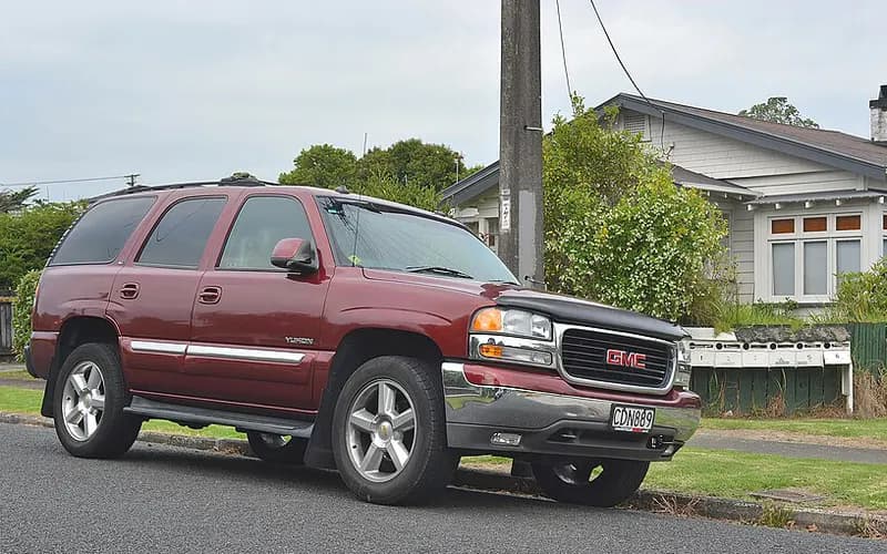
Common on this vehicle:Warning lightLeakNoiseVibration or shudderMisfire or rough idleGauge or instrument faultAir conditioning or heaterCorrosion or rust
Possible causes
47 causes not drawn
- Intake manifold gasket leak (cold idle misfire, lean codes)1
- P0300 after engine repairs: injector connectors crossed (cylinders 5-7 / 6-8)1
- Slight roughness at idle with no DTCs (possible characteristic)1
- Throttle body carbon build-up: idle surge, reduced engine power, throttle DTCs (high mileage)1
- Stability System Disabled message and unwanted StabiliTrak activation (tire wear or mismatched tires)1
- OnStar Module: electrical fault1
- Aftermarket part (not the vehicle as built): Federal-Mogul National / Carquest replacement wheel hub assembly retention nut - recall 07E-1062WD only1
- Grease seen at front hub bearing seals (normal purge, do not replace)1
- Creak or squeak noise from the rear lower control arm bushings (do not replace the propshaft)1
- Upper control arm bracket alignment (dowel) pin missing at front end alignment1
- Ground Ring Terminal: loose or misadjusted3
- Intermittent stall, misfire or crank no start (Ignition 1 feed wire broken near C148/C149)2
- Vehicle Communication Interface Module: electrical fault, software2
- Intermittent MIL, service lamps/messages or DTCs from connector fretting corrosion1
- Navigation radio returned from the Electronic Service Center: no navigation and CD ERROR message1
- No crank with a blown Ign A fuse (circuit 142 pinched at the steering column support bracket)1
- Radio shows a disc error when a media disc is inserted (unsupported disc format or damaged disc)1
- DRLs or auto headlamps will not disable with the headlamp switch (Canada, RPO Z49; normal)1
- Steering intermediate shaft clunk3
- Power steering pump whine between idle and 2000 rpm1
- Headliner sagging (hook and loop patch detached; reattach with epoxy)2
- Power Folding Mirror: failed2
- Bench seat (RPO AE7) center console armrest hinges broken (replace the lid, not the console assembly)1
- Door sags or is hard to open or close (worn or corroded hinge pins and bushings)1
- Front seat adjuster switch knob loose or missing (replace only the switch cover)1
- Double vision or ghost image in the driver's auto dimming outside mirror (normal)1
- Mirror Glass: broken, loose or misadjusted2
- Sunroof: failed2
- HVAC blower motor resistor module / connector overheating2
- No passenger compartment air filter (not available from the 2003 model year; normal)2
- HVAC actuator clicking / ticking noises (recalibrate the HVAC control module, do not replace actuators)1
- Rear HVAC ticking noise, no rear temperature or mode control, DTC B0434 / B3764 (revised auxiliary HVAC control module)1
- Climate Control Module: software1
- Seat Belt Buckle: clogged or contaminated, failed2
- SIR lamp on and inside mirror temperature/compass display inoperative (open air bag fuse, circuit 1139 shorted to ground)1
- Air bag (SIR) lamp on with DTC B1001 after BCM or SDM replacement1
- Seat Belt Warning Light: failed1
- 4L60-E burnt 3-4 clutch pack1
- 4L60-E slip or no forward engagement right after input housing replacement (service part 17803687)1
- 4L80-E / 4L85-E planetary gear whine in first and second gear1
- Electronic transfer case stops shifting with no DTC (shift abuse lock out mode, normal)1
- Transfer case speed sensor connector locks bend on disconnect (improved connector)1
- 4L60-E / 4L65-E clunk on 2-3 upshift or 3-2 downshift (normal condition)1
- Grind / ratchet noise when shifting into Park in 4LO (characteristic)1
- Coolant leak at the rear of the vehicle (auxiliary heater hose quick connector)1
- Fuel gauge reads low or drops to empty in Park / Neutral (normal characteristic)1
- Tire and loading information label lists inaccurate vehicle capacity weight (FMVSS 110) - recall 05V-5521
Causes with no correction stated (18)
Causes the records name for which no check or repair is stated, in a technical document or in a record. Press one for the records that name it.
- Electrical, wiring and power
- Fuse: failed, electrical fault (4)Intermittent no start with Service Stability, ABS light, 'Unknown Driver' and multiple DTCs / no module communication (2)Cable: overheated (1)Powertrain Control Module: software (1)
- Transmission and driveline
- Transmission: failed, clogged or contaminated (3)Rear Axle: failed (2)Axle Differential Seal: leaking (1)Locking Rear Differential (1)
- Airbags and seat belts
- Airbag: failed (2)
- Other
- Bolt: broken (2)
- Body, doors and interior
- Locking Mechanism: design or manufacturing, failed (2)Camper Mirror: design or manufacturing (1)
- Heating and air conditioning
- HVAC temperature doors default to full hot or defrost cannot be obtained (1)
- Brakes
- Service Stability message with DTC C0131, C0196, C0290 and/or C0292 (1)Electronic Brake Control Module: software (1)Wheel Speed Sensor: corroded (1)
- Audio and telematics
- CD Changer: failed (1)
- Exhaust and emissions
- Exhaust Manifold Bolt: broken (1)
The documents say what to doOnly records name itThe size of a node, the width of a link and the numbers are records matching this search, not likelihoods.
FaultCrate・GMC Yukon 2000–2006・2006
Candidate cause (the documents say what to do)
Hydro-boost brake assist and power steering share one hydraulic supply (four campaigns)
Some vehicles were built with an out-of-specification hydro-boost housing relief valve bore.
The hydraulic brake booster pressure accumulator may crack and separate from the hydro-boost assembly during normal operating conditions.
What to do
- Perform the "Power Steering System Test" found in SI and make any necessary repairs based on system diagnosis.
- To tell whether a 670 gear box is fitted, inspect the mounting bolts that attach the stub shaft housing; a 670 gear box has only 3 mounting bolts.
- The PI document instructed technicians to diagnose the vehicle using the Power Steering Test Procedures if an owner complained about difficulty steering during "parking lot type maneuvers"; if the vehicle passed this test, no work was required, as GM viewed this as a normal phenomenon.
- Dealers replace the hydro-boost relief valve.
- Dealers test the hydro-boost assembly for functional operation and replace it if it fails.
- Dealers replace the hydraulic pump.
Caution: An inoperative pump raises steering and braking effort but does not completely remove the ability to steer or slow the vehicle.
What is needed
- Parts and materials
- Hydro-boost relief valve
- Hydro-boost assembly (if it fails the functional test)
- Hydraulic pump
- Power steering hoses (those with a suspect date code)
- Power Steering Gear 88965542, Union Fitting 26025709, Inlet O-ring Seal 26001594 (C/K 1500 series only)
- Replacement pressure control valve PN 26095470 (available, if the customer's situation warrants, to provide additional steering assist)
Part numbers printed in the document
88965542Gear, Steering (Remanufacture)Look up at RockAuto (aftermarket candidates) ↗Search the web ↗
Replaced by: 19330495as stated by GMPartsGiant (checked 2026-10-06) ↗Look up at RockAuto (aftermarket candidates) ↗Search the web ↗
26025709Fitting,P/S PumpLook up at RockAuto (aftermarket candidates) ↗Search the web ↗
No successor statedas stated by GMPartsGiant (checked 2026-10-06) ↗
26001594Seal,P/S Fluid Cooling Pipe(O Ring)Look up at RockAuto (aftermarket candidates) ↗Search the web ↗
No successor statedas stated by GMPartsGiant (checked 2026-10-06) ↗
26095470Look up at RockAuto (aftermarket candidates) ↗Search the web ↗
The numbers are as the document prints them. The name and the replacing number are what the pages of GMPartsGiant, a reseller of genuine parts and not GM, state. Aftermarket equivalents are not checked here (the links only search by number). Confirm the fit for the vehicle (VIN) before ordering.
- Labor time
- Not stated
- Special tools
- Not stated
- Scan tool
- Not stated
Only what the technical documents state. "Not stated" does not mean not needed.
In the records
- Line: replaced 3
- Power Steering Pump: replaced 3
- Power Steering Line: replaced 1
See the evidence (2 technical documents, 7 records)
Passages of the technical documents
Some vehicles were built with an out-of-specification hydro-boost housing relief valve bore.
SOME OF THESE VEHICLES WERE PRODUCED WITH AN OUT-OF-SPECIFICATION BRAKE HYDRO-BOOST HOUSING RELIEF VALVE BORE.
NHTSA (recall summary text as published by NHTSA)
The valve O-ring seal may fracture, and steering effort may be slightly higher while braking or parking.
CONSEQUENTLY, THE VALVE O-RING SEAL MAY FRACTURE. STEERING EFFORTS MAY BE SLIGHTLY INCREASED WHILE BRAKING OR PARKING.
NHTSA (recall summary text as published by NHTSA)
Dealers replace the hydro-boost relief valve.
DEALERS ARE TO REPLACE THE HYDRO-BOOST RELIEF VALVE.
NHTSA (recall summary text as published by NHTSA)
The hydraulic brake booster pressure accumulator may crack and separate from the hydro-boost assembly during normal operating conditions.
THE HYDRAULIC BRAKE BOOSTER PRESSURE ACCUMULATOR MAY CRACK AND SEPARATE FROM THE HYDRO-BOOST ASSEMBLY DURING NORMAL OPERATING CONDITIONS.
NHTSA (recall summary text as published by NHTSA)
Manufacturer’s documents
- Power Steering Hose Fracture 05086A 2005-05-10
A cause or a result a complaint states is the owner’s view or what a dealer told them, not an established fact.
Put together by FaultCrate from public records and technical documents. The cause and the repair are for the workshop to decide with the vehicle in front of it. Counts are records, not failure rates.