Source reference 10245395
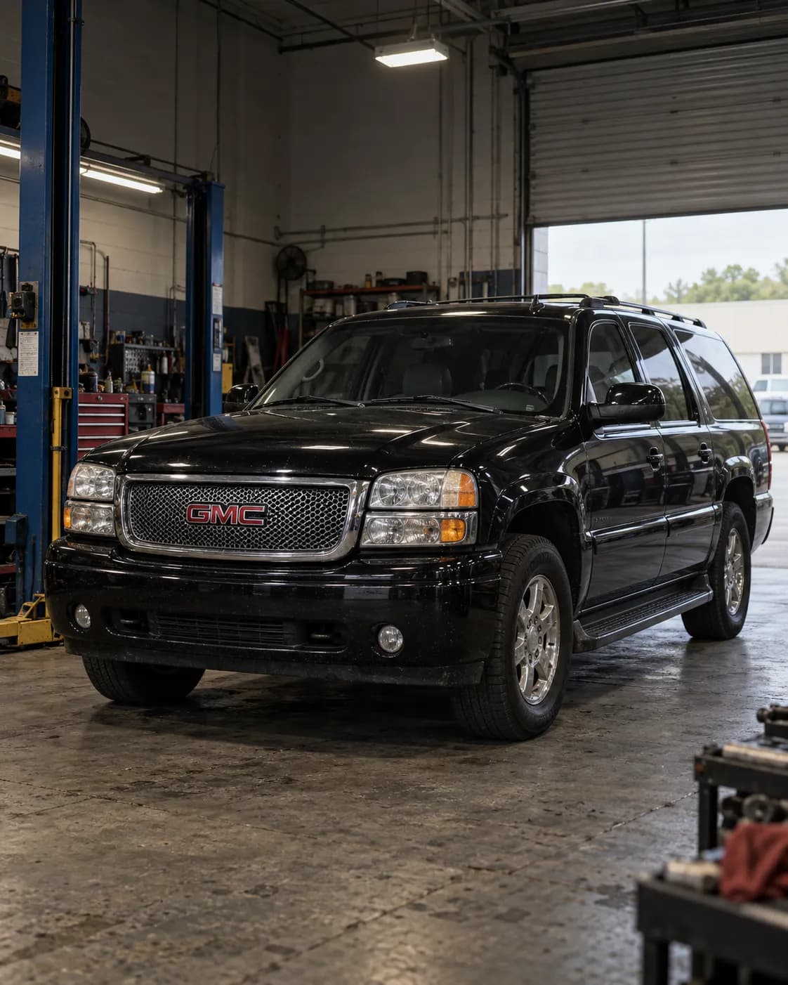
Manufacturer communication — 2006 GMC YUKON DENALI XL
Relation to the target vehicle
- The source's vehicle field includes the trim.
- Model year
- Match 2006 — Source vehicle field
- Model
- Match YUKON DENALI XL — Source vehicle field
- Trim
- Match Denali — Source vehicle field
What the manufacturer’s document says
03-00-91-001I ・ information ・ for GM vehicles in general
Applies to
Applies to 2024 and prior GM passenger cars and trucks.
the passage
Models: 2024 and Prior GM Passenger Cars and Trucks
Finding the cause
Steps to confirm (in the document’s order)
When diagnosing vibration, use the worksheet together with the Vibration Analysis - Road Testing procedure in the service information.
the passage
When diagnosing vibration concerns, use the following worksheet in conjunction with the appropriate Vibration Analysis-Road testing procedure in the Vibration Correction sub-section in SI.
Place the sensor where the vibration is felt: on the seat track for a seat complaint, on the steering column for a steering wheel complaint.
the passage
if the vibration complaint is from the seat then place the sensor on the seat track, if the vibration complaint is from the steering wheel then attach the sensor to the steering column.
Moving the sensor to other areas, look for the same Hz reading with the greatest amplitude.
the passage
The key is to look for the same Hz reading with the greatest amplitude mg readings.
If a system balance was attempted and the vibration remains, check ring gear backlash at each tooth; readings should not vary more than 0.050 mm (0.002 in).
the passage
check the ring gear backlash at each tooth of the ring gear. Note that excessive ring gear runout may result in a first order tire speed or first order prop shaft speed concern. Backlash at each tooth on the ring gear (readings should not vary more than 0.050 mm (0.002 in)):
Aluminum wheel/tire runout measured on the vehicle: maximum 0.030 in (.762 mm).
the passage
Aluminum Wheel/Tire Runouts on vehicle (max. 0.030 in (.762 mm))
Hub mounting surface runout: maximum 0.005 in (0.132 mm).
the passage
Hub Mounting surface runouts (max. 0.005 in (0.132 mm))
Wheel stud runout: maximum 0.010 in (0.254 mm).
the passage
Wheel stud runouts (max. 0.010 in (0.254 mm))
Compiled by reading the full text of the document; each point stands on the passage shown. Check the document itself, linked below, before working on a vehicle.
Stated content
Communication summary
本技術情報は、振動の問題を診断する際に、整備士が適切な振動分析-ロードテスト手順と併せて使用できる振動分析ワークシートを提供する。 Machine translation (unreviewed)
This service bulletin provides a vibration analysis worksheet the technician can use in conjunction with the appropriate Vibration Analysis-Road testing procedure when diagnosing vibration concerns.
Go to this passage in the original
Source
- Source
- NHTSA Manufacturer Communications
- Source reference
- 10245395
- Received by source
- 2023-11-22
- Incident date
- Unknown
Open original text and sourceOpen the provider's page (external)